Prosthetic disc for intervertebral insertion

a technology of prosthesis and disc, applied in the field of medical devices and methods, can solve the problem that the movement of the core relative to the plate will preferably be unconstrained, and achieve the effect of low friction

Active Publication Date: 2016-09-01
SIMPLIFY MEDICAL PTY LTD
View PDF2 Cites 28 Cited by
  • Summary
  • Abstract
  • Description
  • Claims
  • Application Information

AI Technical Summary

Benefits of technology

[0011]In one aspect of the present invention, a prosthetic disc for insertion between adjacent vertebrae includes upper and lower plates having outer surfaces, which engage and are locatable against the respective vertebrae, and inner curved surfaces. A core is disposed between the curved surfaces to allow the plates to slide over the core. Preferably, the plates can slide freely in all directions, not being limited to movement in a single direction as with the prior art. The present invention further provides peripheral restraining structure on one or both of the plates or the core to hold the core against the curved surface of at least one of the plates during sliding movement of the plates over the core. The peripheral restraining structure defines a limit or boundary for movement of the core relative to at least one of the upper and lower plates. Within such a peripheral boundary, however, movement of the core relative to the plate will preferably be unconstrained. That is, movement of the core relative to the plate may occur in any direction without significant inhibition or friction. The core will preferably not be attached to either the upper or lower plate, and the plates will thus be able to freely articulate relative to each other over the core, which provides a low friction bearing surface.
[0012]An advantage of the structure thus described is that the surface contact area between the core and each of the upper and lower plates may be maximized. By providing only a peripheral restraint, as opposed for example to grooves and keys on the surface of the core and plates, the width or diameter of the core relative to the size of the plate may be maximized. Moreover, the surfaces of the core and the plates which contact each other may be made smooth and free from other structure(s) that might adversely affect performance. In the preferred embodiments, both the curved surfaces of the plates and the corresponding surfaces of the core will be spherical sections. The use of spherical surfaces promotes free, unconstrained relative motion of the plates and the core in all directions.
[0013]In some embodiments, the peripheral restraining structure limits relative inclination of the plates during sliding movement of the plates over the core, usually by defining a stop structure. In other embodiments, the peripheral restraining structure lifts one side of the core relative to an opposite side of the core during sliding movement of the plates over the core. The peripheral restraining structure itself may take any of a number of different forms. In one embodiment, for example, the restraining structure comprises a ring structure on at least one of the upper and lower plates and an annular structure on at least a portion of the periphery of the core. The ring structure will be adapted to engage and restrain the annular structure on the core. For example, the ring structure may comprise a flange which defines an overhang over at least a portion of the periphery of one of the plates. The overhang of the flange will receive the annular structure on the core to provide an interference fit which retains the core against the curved surface of the plate but allows the core to slide freely and in an unconstrained manner within the limit or boundary defined by the flange. The annular structure on the core may be a rim which extends continuously or discontinuously (preferably continuously) around a lateral circumference of the core. By providing a rim which has a width, usually a diameter, which is slightly greater than the corresponding width of an inner edge of the flange at one point, the core will be held in place and will not be dislodged from the cavity defined by the ring structure in normal use.
[0015]The upper and lower plates may be made of any suitable material or combination of materials, such as but not limited to cobalt chrome molybdenum and titanium. In some embodiments, titanium plates are used, and these plates may optionally include inner surfaces of titanium nitride and outer surfaces that are aluminum oxide blasted to create micro-concavities. In another embodiment, cobalt chrome plates are used, with the outer surfaces being blasted with aluminum oxide and then coated with a titanium plasma spray. In some embodiments, the plates comprise an MRI-compatible material, such as titanium, coupled with a hardened material, such as cobalt chrome molybdenum. Such materials may be coupled using any suitable means, such as laminating, slip fitting, interferences fitting, adhesion, welding, molding or the like. Some plates include a coating or material on the inner surfaces for reducing friction and / or wear and tear, such as a titanium nitride surface.

Problems solved by technology

Within such a peripheral boundary, however, movement of the core relative to the plate will preferably be unconstrained.

Method used


Image

  • Prosthetic disc for intervertebral insertion
  • Prosthetic disc for intervertebral insertion
  • Prosthetic disc for intervertebral insertion

Examples


Embodiment Construction

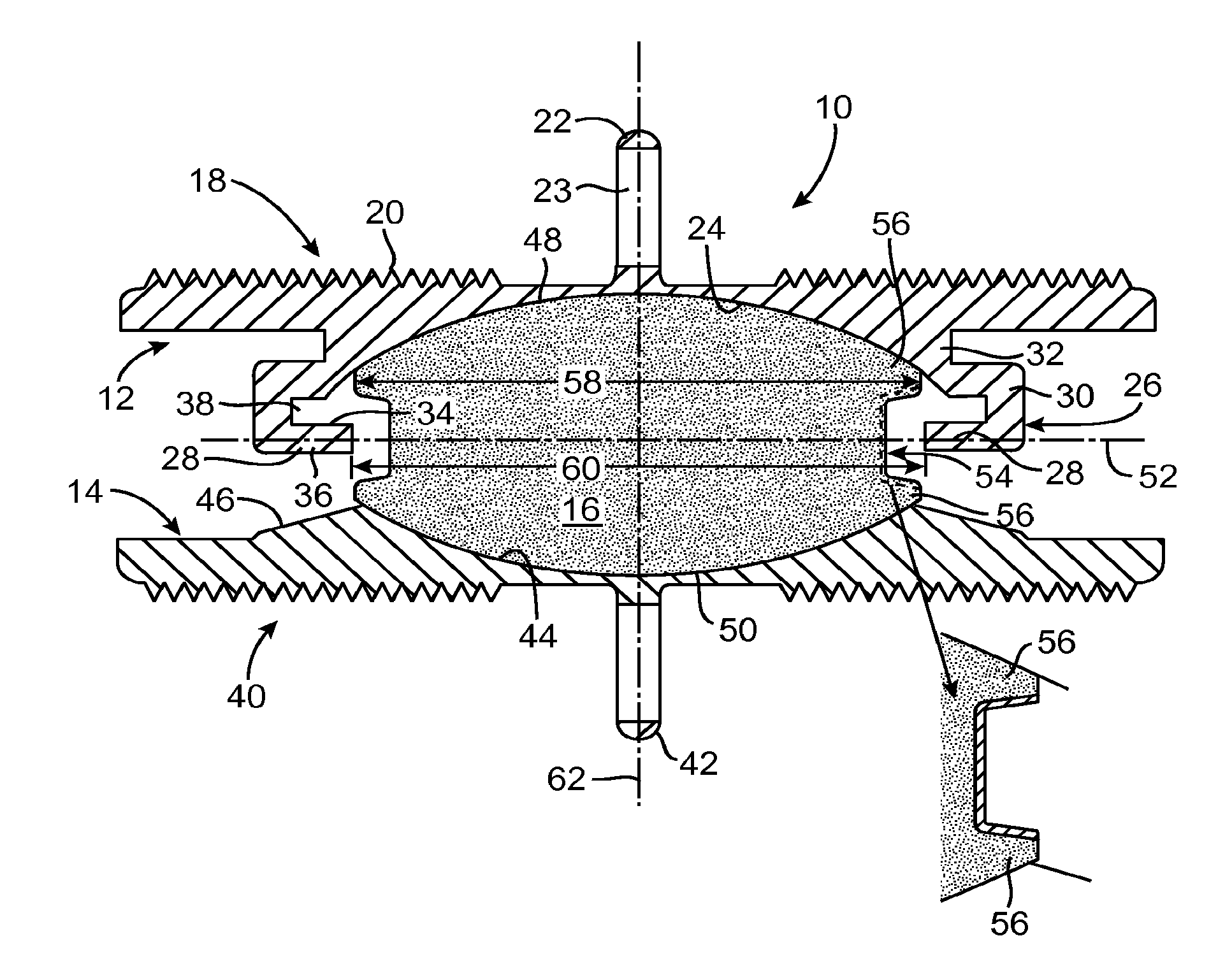
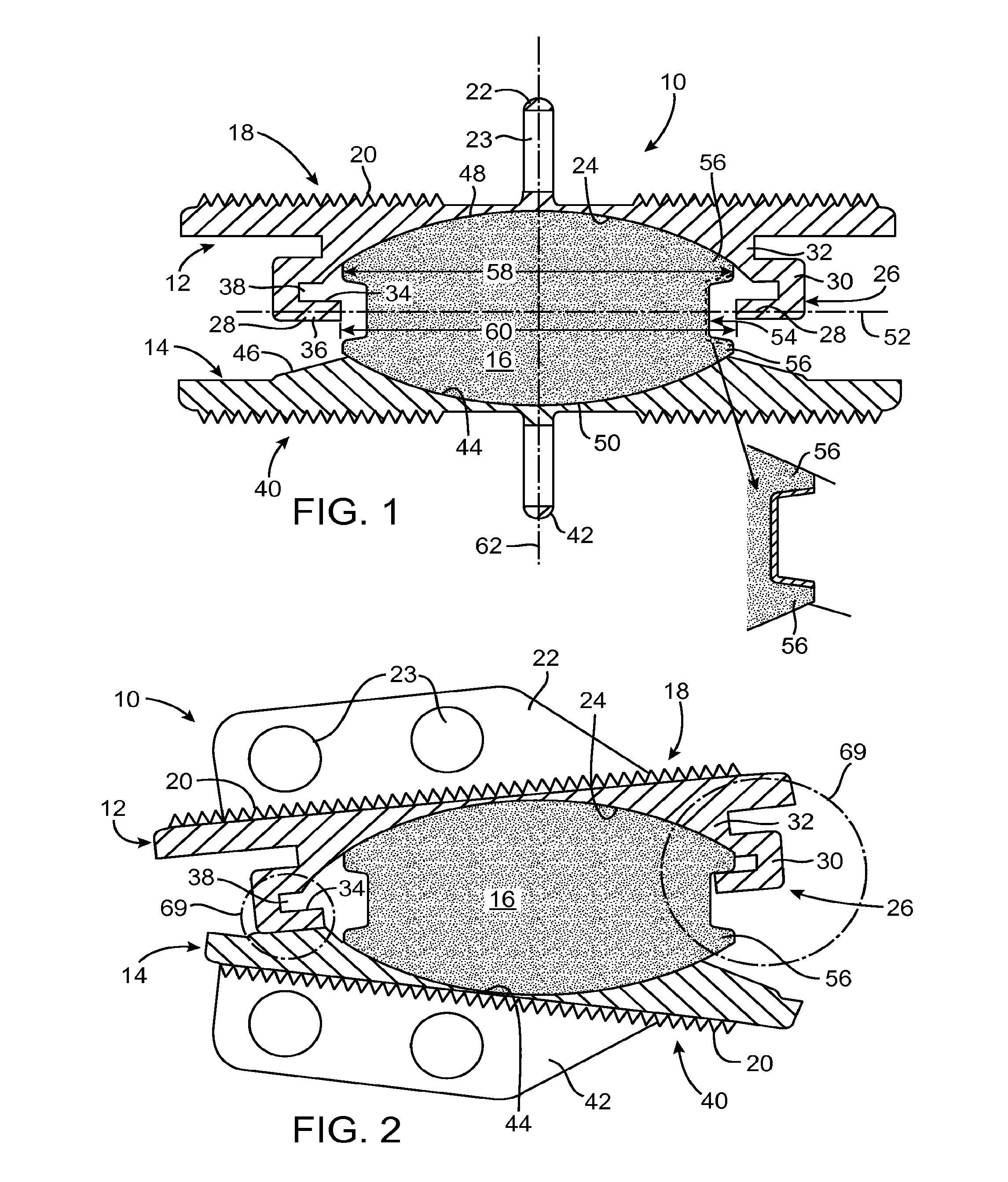
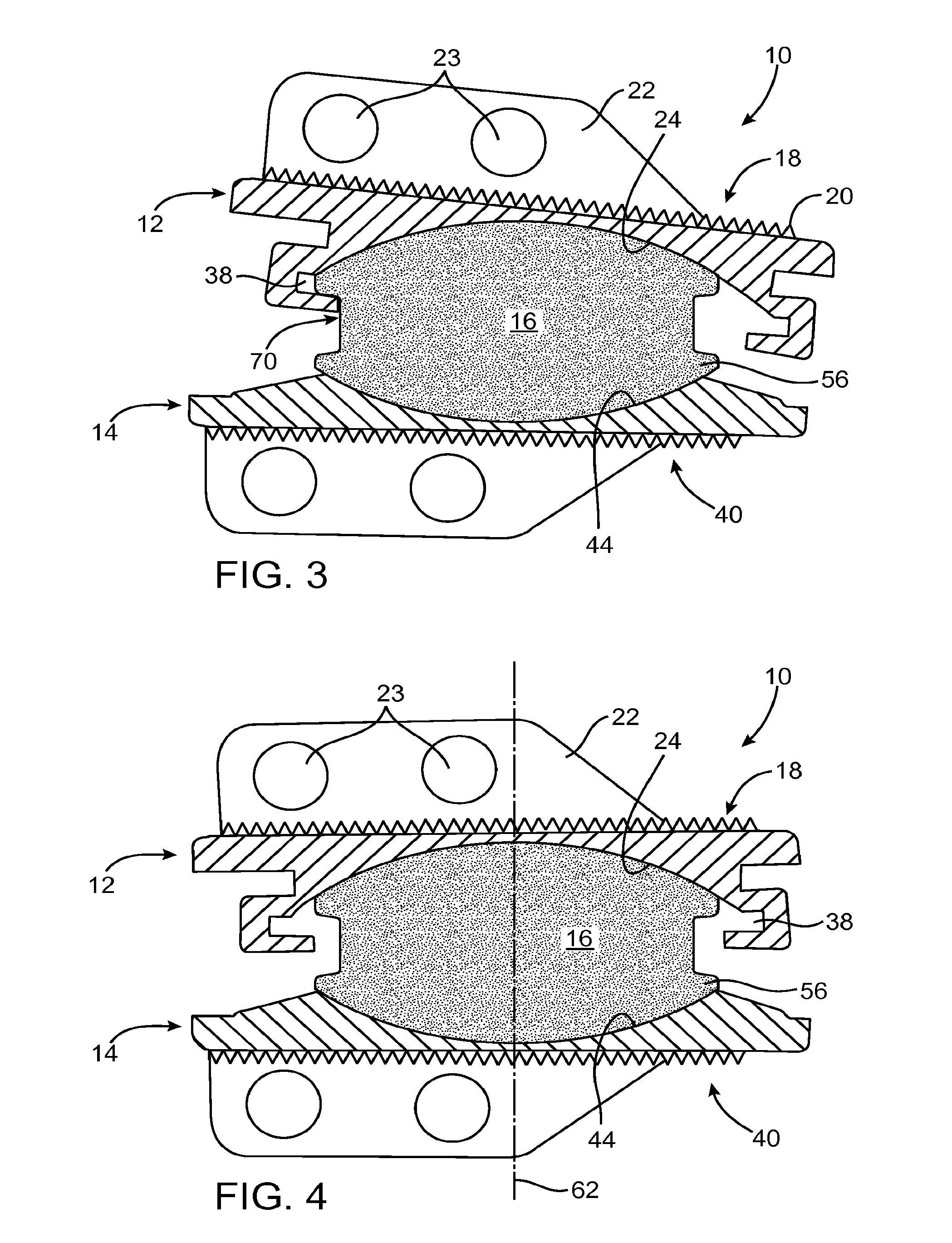
[0030]FIGS. 1 to 4 illustrate a prosthetic disc 10 for intervertebral insertion between two adjacent spinal vertebrae (not shown). The disc 10 comprises three components, namely an upper plate or shell 12, a lower plate or shell 14 and a core 16 located between the plates.

[0031]The upper plate 12 includes an outer surface 18 and an inner surface 24 and may be constructed from any suitable material or combination of materials, such as but not limited to cobalt chrome molybdenum, titanium (such as grade 5 titanium) and / or the like. In one embodiment, typically used in the lumbar spine, the upper plate 12 is constructed of cobalt chrome molybdenum, and the outer surface 18 is treated with aluminum oxide blasting followed by a titanium plasma spray. In another embodiment, typically used in the cervical spine, the upper plate 12 is constructed of titanium, the inner surface 24 is coated with titanium nitride, and the outer surface 18 is treated with aluminum oxide blasting. An alternativ...


PUM


Abstract

A prosthetic disc for insertion between adjacent vertebrae includes a core having upper and lower curved surfaces, upper and lower plates, and peripheral restraining structure on at least one of the upper plate, the lower plate and the core. Each plate has an outer surface which engages a vertebra and an inner curved surface which slides over the curved surface of the core. The peripheral restraining structure serves to hold the core against a curved surface of at least one of the plates during sliding movement of the plates over the core.

Description

CROSS-REFERENCE TO RELATED APPLICATION[0001]The present application is a continuation of U.S. patent application Ser. No. 14 / 612,431 (Attorney Docket No.29850-704.305), filed Feb. 3, 2015, which is a continuation of U.S. patent application Ser. No. 14 / 150,437 (Attorney Docket No. 29850-704.304), filed Jan. 8, 2014 (now U.S. Pat. No. 8,974,533), which is continuation of U.S. patent application Ser. No. 12 / 626,027 (Attorney Docket No. 29850-704.302), filed Nov. 25, 2009, (now U.S. Pat. No. 8,845,729), which is a continuation of U.S. patent application Ser. No. 10 / 855,253 (Attorney Docket No. 29850-704.201), filed May 26, 2004, (now U.S. Pat. No. 7,753,956), which application claims the benefit of U.S. Provisional Application No. 60 / 473,802 (Attorney Docket No. 29850-704.101) and 60 / 473,803 (Attorney Docket No. 29850-703.101), both filed May 27, 2003; all of which are incorporated herein by reference in their entirety.BACKGROUND OF THE INVENTION[0002]1. Field of the Invention[0003]This...

Claims


Application Information

Patent Timeline
Patent Type & Authority Applications(United States)
IPC IPC(8): A61F2/44
CPCA61F2/4425A61F2002/5098A61F2002/443A61F2002/3008A61F2002/30131A61F2002/30245A61F2002/30299A61F2002/30518A61F2002/30649A61F2002/30785A61F2002/30822A61F2002/30838A61F2002/30884A61F2002/30904A61F2310/00179A61F2230/0076A61F2/442
Inventor DE VILLIERS, MALANHAHNLE, ULRICH
Owner SIMPLIFY MEDICAL PTY LTD
Why Eureka
Try Eureka