Machining head for a gear cutting machine and method for toothing a workpiece, in particular a worm shaft or toothed rack

a gear cutting machine and workpiece technology, applied in the direction of gear teeth, gear teeth, manufacturing tools, etc., can solve the problems of high gear ratio, low efficiency of worm gear units at the same time, and inability to accommodate worm b>5/b> in its center, etc., to achieve a larger advance and feed rate

Inactive Publication Date: 2016-09-01
LIEBHERR VERZAHNTECHNIK GMBH
View PDF12 Cites 5 Cited by
  • Summary
  • Abstract
  • Description
  • Claims
  • Application Information

AI Technical Summary

Benefits of technology

[0014]According to the present disclosure, there is proposed a machining head for a gear cutting machine, in particular a hobbing or hob grinding machine, for toothing and machining a workpiece, which may be in the form of a worm shaft for a worm gear unit or a toothed rack. In a way essential for the present disclosure, the machining head is equipped with at least one additional tool spindle, and the machining head hence comprises at least two tool spindles arranged one beside the other for accommodating corresponding tools. Accordingly, it no longer is necessary to accommodate several tools on one and the same spindle, although this should of course not be excluded for the novel machining head.
[0015]The division of the machining tools on two separate tool spindles arranged one beside the other provides far-reaching advantages in the tooth-machining of workpieces. In particular in workpieces of great overall length, an additional fixation can be effected at the tip of the workpiece beside the conventional clamping of the workpiece on the machine table, due to the division of the tools on separate tool axles, whereby the workpiece can be accommodated much more stably. The machining quality can distinctly be improved thereby. In addition, the more stable fixation allows larger advances or feed rates, whereby the machining time can noticeably be reduced. Furthermore, a limited spindle length is sufficient to accommodate a single tool, which ensures a more stable tool travel even without counter bearing.
[0016]The workpiece may be clamped in a vertical longitudinal direction.
[0017]The arrangement of the at least two tool spindles may be substantially parallel to each other. The drive of the at least two tool spindles can be effected via separate motors or alternatively via a common motor. When using a common drive unit, the division of moments may be achieved via an interposed transfer gear. When using separate drive units, in particular direct drives are suitable for the individual spindles. The machining head optionally comprises a guiding device for a shiftable accommodation of the machining head within a gear cutting machine. The axis of rotation of the tool spindle in this case may extend transversely to the shift direction of the machining head achievable by means of the guiding device.
[0022]In an advantageous configuration of the gear cutting machine, the same comprises at least one tip, in particular a tip mounted on a ball bearing, for fixing the workpiece clamped on a machine table during machining with the machining head. Other than known from the prior art, workpieces with a certain axial length accordingly can be clamped on the tool table with sufficient stability and thereby provide for gear cutting in a stable and quality-preserving way. Alternatively or in addition, the fixation via at least one steady rest likewise is conceivable.
[0030]After at least two side milling cutters are mounted on the machining head, a roughing and a finishing step can be carried out with the two milling cutters in one machining step for adjacent tooth gaps. The position of the tools relative to each other is adjusted via special tool holders. These tool holders should differ in their length exactly by the gap distance of the tooth gaps. In the case of tool sets, the length of the tool holders should be chosen corresponding to the number of tool sets and the tooth gap machined therewith.

Problems solved by technology

Due to the function-related relative movements in screw rolling gear units, a sliding movement takes place above all between the flanks of worm and worm gear, so that worm gear units have a low efficiency at high gear ratios at the same time.
Further methods include the hob peeling or whirling of worms, wherein the disadvantage of these methods is to be seen in the expensive special tools adjusted especially to the workpiece to be manufactured.
A serious disadvantage of this embodiment consists in that because of impending collisions the worm 5 cannot accommodate in its center via a tip.
Especially with small tool diameters and long worms 5 the tool mandrel 3 can become quite thin, which has a disadvantageous effect on the stability.
However, when tools with large diameter are used, an offset arrangement on the spindles extending in parallel possibly can be expedient, as otherwise the large diameters and the possibly overlapping working radii can lead to a collision of the two tools.

Method used


Image

  • Machining head for a gear cutting machine and method for toothing a workpiece, in particular a worm shaft or toothed rack
  • Machining head for a gear cutting machine and method for toothing a workpiece, in particular a worm shaft or toothed rack
  • Machining head for a gear cutting machine and method for toothing a workpiece, in particular a worm shaft or toothed rack

Examples


Embodiment Construction

[0039]FIGS. 1, 2 have already been discussed in detail in the introductory part of this description. FIG. 3 shows a worm shaft 5 with a side milling cutter 2 in engagement. The flank angle of the side milling cutter 2 is designated with the angle α0, while the helix angle of the worm shaft 5 is designated with γm.

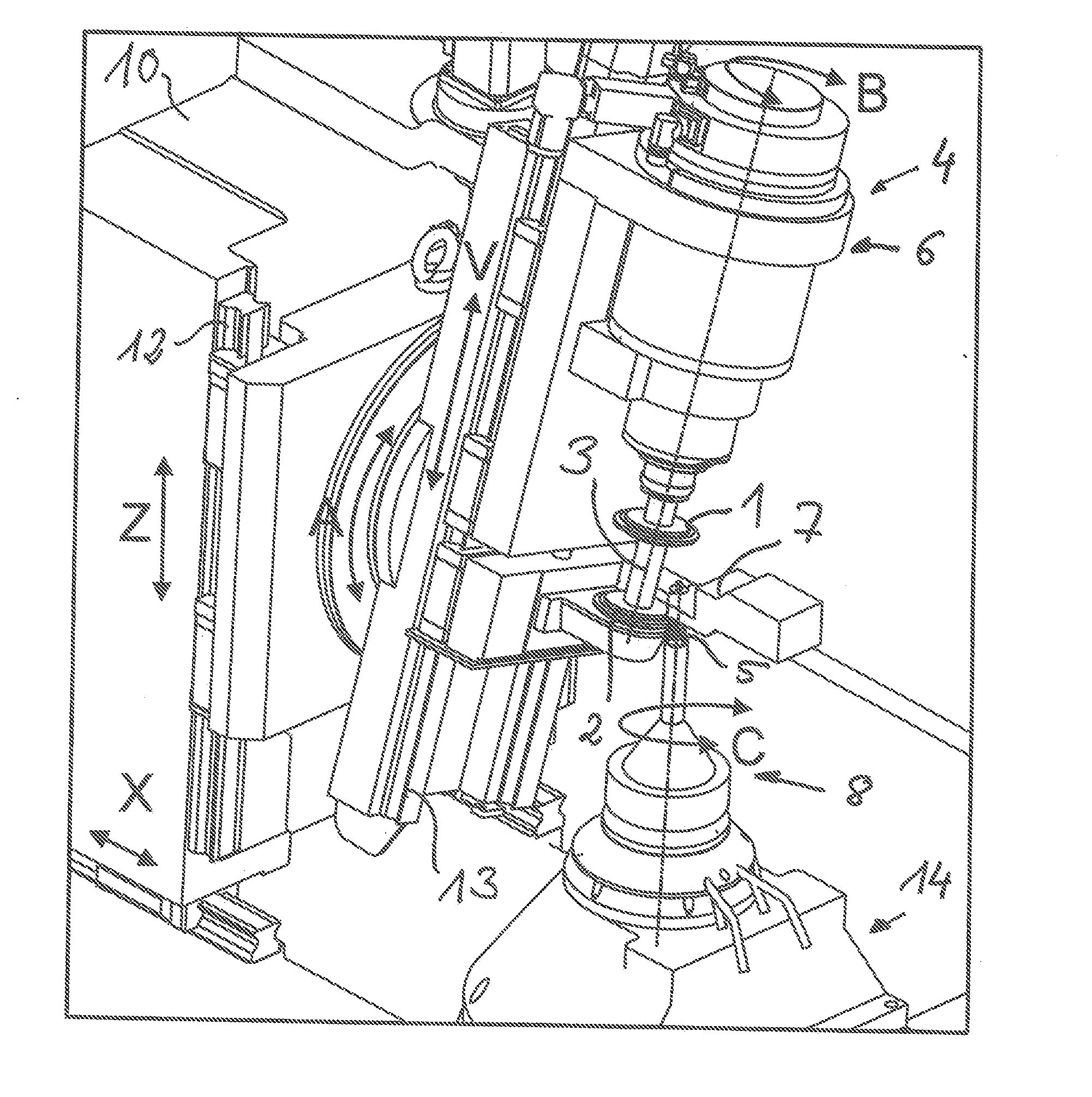
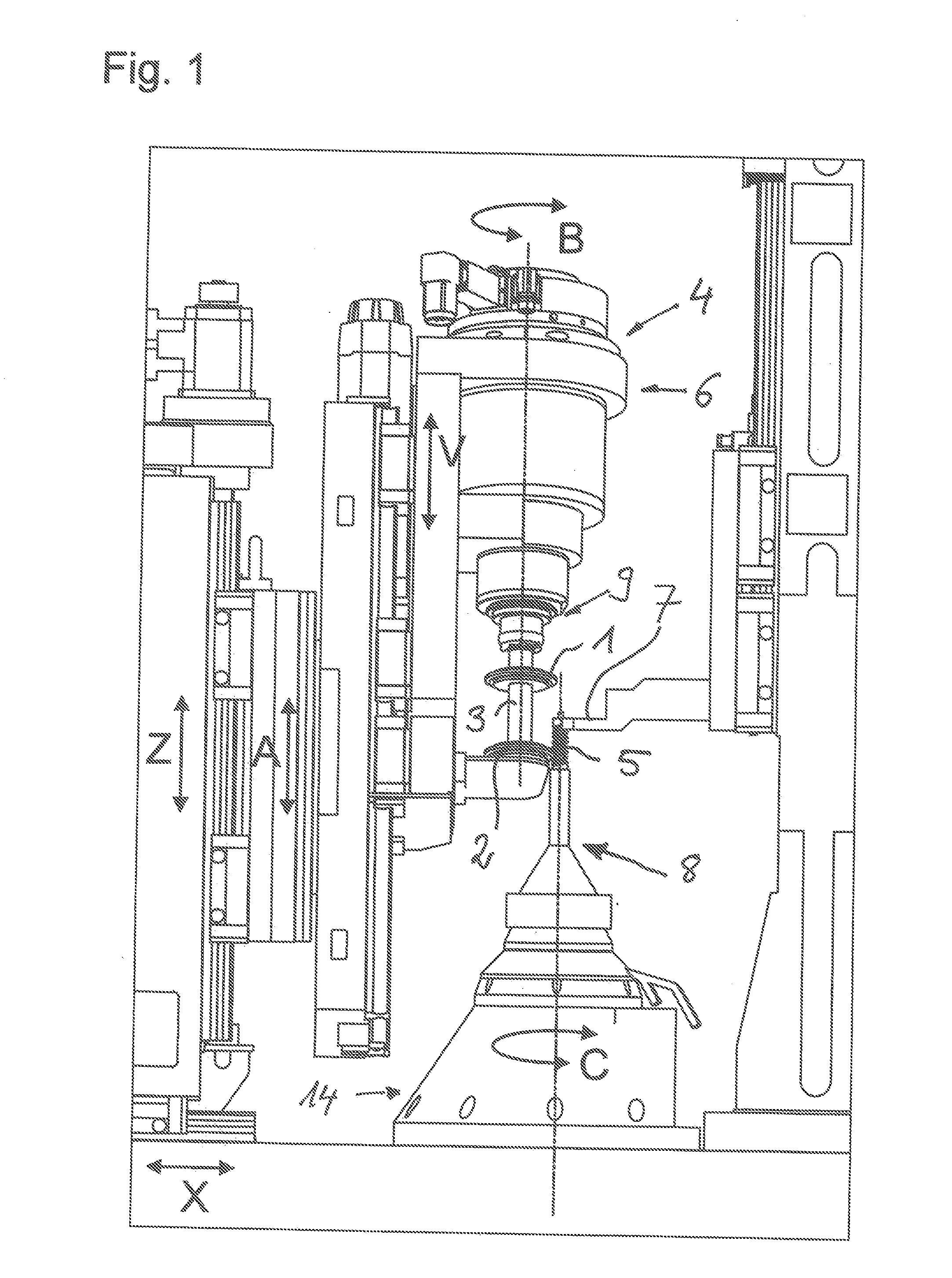
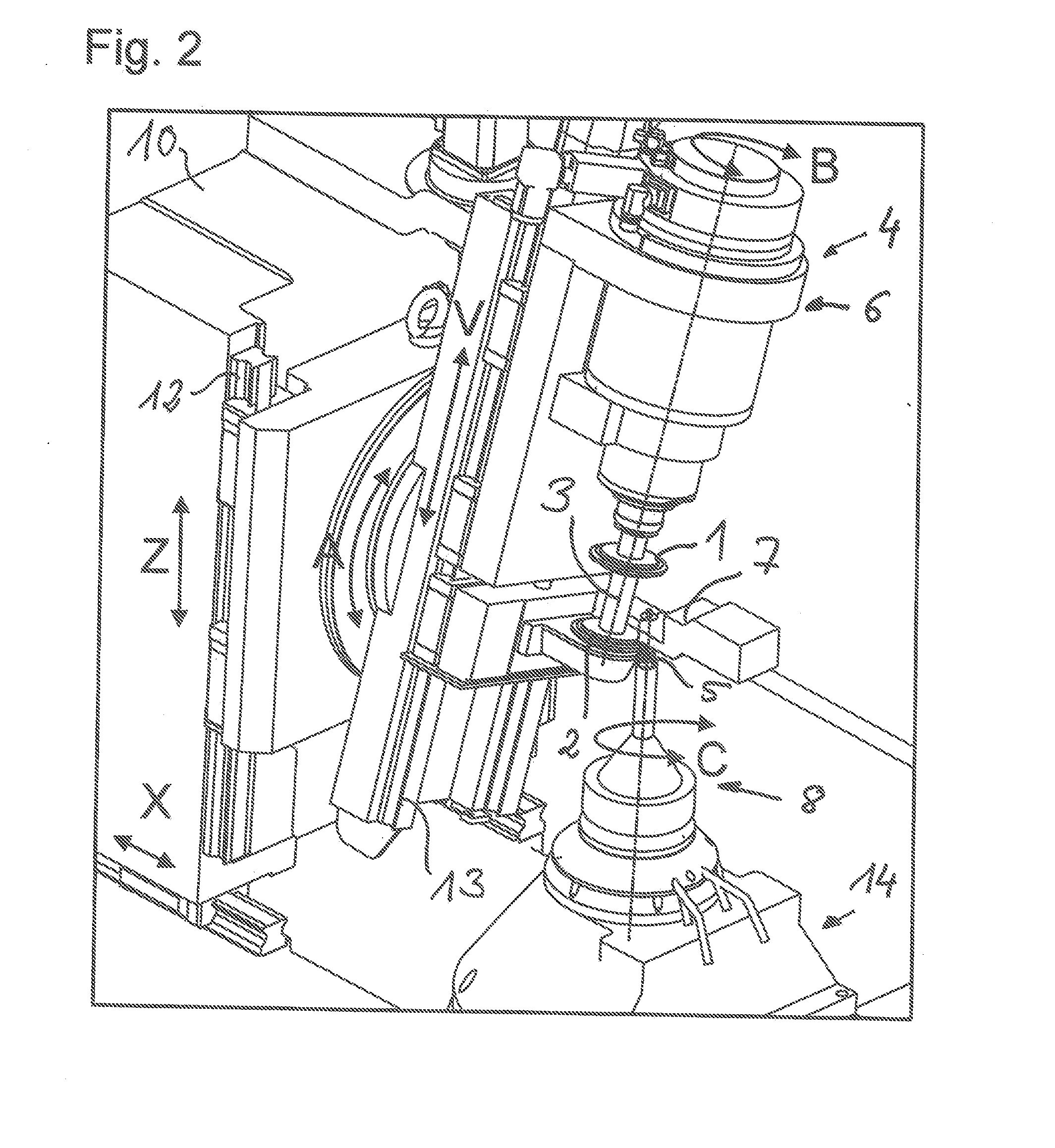
[0040]FIG. 4 shows a perspective view of the gear cutting machine according to the present disclosure with the machining head 60 of novel construction. Except for the machining head 60, the illustrated gear cutting machine corresponds to a known hob and profile grinding machine with the degrees of freedom necessary for machining. In detail, the CNC machine can perform the indicated movements A, B, C, V, X, Z, wherein the X-axis designates the radial movement of the column carriage 10 in direction of the vertically clamped workpiece 5, V designates the tangential movement or shift movement of the tool 1, 2 or the machining head 60 by means of the tangential carriage 13 relat...


PUM

PropertyMeasurementUnit
distanceaaaaaaaaaa
distancesaaaaaaaaaa
diametersaaaaaaaaaa

Abstract

The present disclosure relates to a machining head for a gear cutting machine, in particular a hobbing or hob grinding machine, for toothing a workpiece, in particular a worm shaft or a toothed rack, wherein the machining head comprises at least two tool spindles arranged one beside the other.

Description

CROSS REFERENCE TO RELATED APPLICATION[0001]This application claims priority to German Patent Application No. 10 2015 002 362.4, entitled “Machining Head for a Gear Cutting Machine and Method for Toothing a Workpiece, in Particular a Worm Shaft or Toothed Rack,” filed on Feb. 26, 2015, the entire contents of which is hereby incorporated by reference in its entirety for all purposes.TECHNICAL FIELD[0002]This present disclosure relates to a machining head for a gear cutting machine, in particular a hobbing or hob grinding machine, for toothing a workpiece, in particular a worm shaft or a toothed rack.BACKGROUND AND SUMMARY[0003]A toothed rack is a vertically mounted technical device with teeth and mostly is used within a rack-and-pinion drive.[0004]Worm gear units are screw rolling gear units which consist of a pairing of a worm (worm shaft) and a helically toothed worm gear meshing therein. In most applications, the axes of worm shaft and worm gear are at right angles to each other. ...

Claims


Application Information

Patent Timeline
Patent Type & Authority Applications(United States)
IPC IPC(8): B23F5/20B23F5/08B23F13/04
CPCB23F5/205B23F5/08B23F13/04B23F5/02B23F5/20B23F13/00B23F23/06B23F17/006B23F21/005
Inventor GEISER, HANSJOERG
Owner LIEBHERR VERZAHNTECHNIK GMBH
Why Eureka
Try Eureka