Mechanically Actuated Cargo Restraint System

Active Publication Date: 2016-09-01
WOLF TECHN SERVICES
View PDF1 Cites 14 Cited by
  • Summary
  • Abstract
  • Description
  • Claims
  • Application Information

AI Technical Summary

Benefits of technology

[0013]Embodiments of the present invention manage the kinetic energy of the user during vehicle acceleration events by stopping the webbing reel during webbing extraction whenever the angular velocity of the webbing reel exceeds a pre-determined design value.
[0014]The advantages of at least some embodiments of the present invention are that it allows movement within the cabin by allowing the webbing to be extended and retracted without any intervention by the user; it can be released after an event allowing the user to continue movement without unhooking the device; using the hook on the device allows it to be moved from place to place within the airframe cabin and hooked to any restraint D-ring. The present invention can be attached and used at any D-ring in the vehicle that is currently used by crewmembers to attach a fixed-length tether. However, it will be appreciated that embodiments with fewer than all of the features will still obtain many of the benefi

Problems solved by technology

Personnel in and on moving vehicles can be subjected to high acceleration environments, such as a crash or quick velocity change that give rise to rapid relative motion between the vehicle and the occupant.
These environments create a risk of injury due to contact with vehicle or equipment structures, and a risk of inadvertent ejection from the vehicle.
The risk of injury is especially pronounced with personnel who cannot be restrained in a typical seat restraint system due to mobility requirements, such as mobile aircrew members within the cargo bays of military helicopters.
The drawbacks to the gunner's belt with a fixed-length tether are that the user is free to flail at any point within the sphere of reach of the tether; some tethers are not adjustable in length; and some tethers must be continually adjusted manually by the user, interrupting critical mission duties.
Fixed-length tether systems allow unwanted free travel of the user at high velocities relative to the vehicle, unwanted contact

Method used


Image

  • Mechanically Actuated Cargo Restraint System
  • Mechanically Actuated Cargo Restraint System
  • Mechanically Actuated Cargo Restraint System

Examples


Embodiment Construction

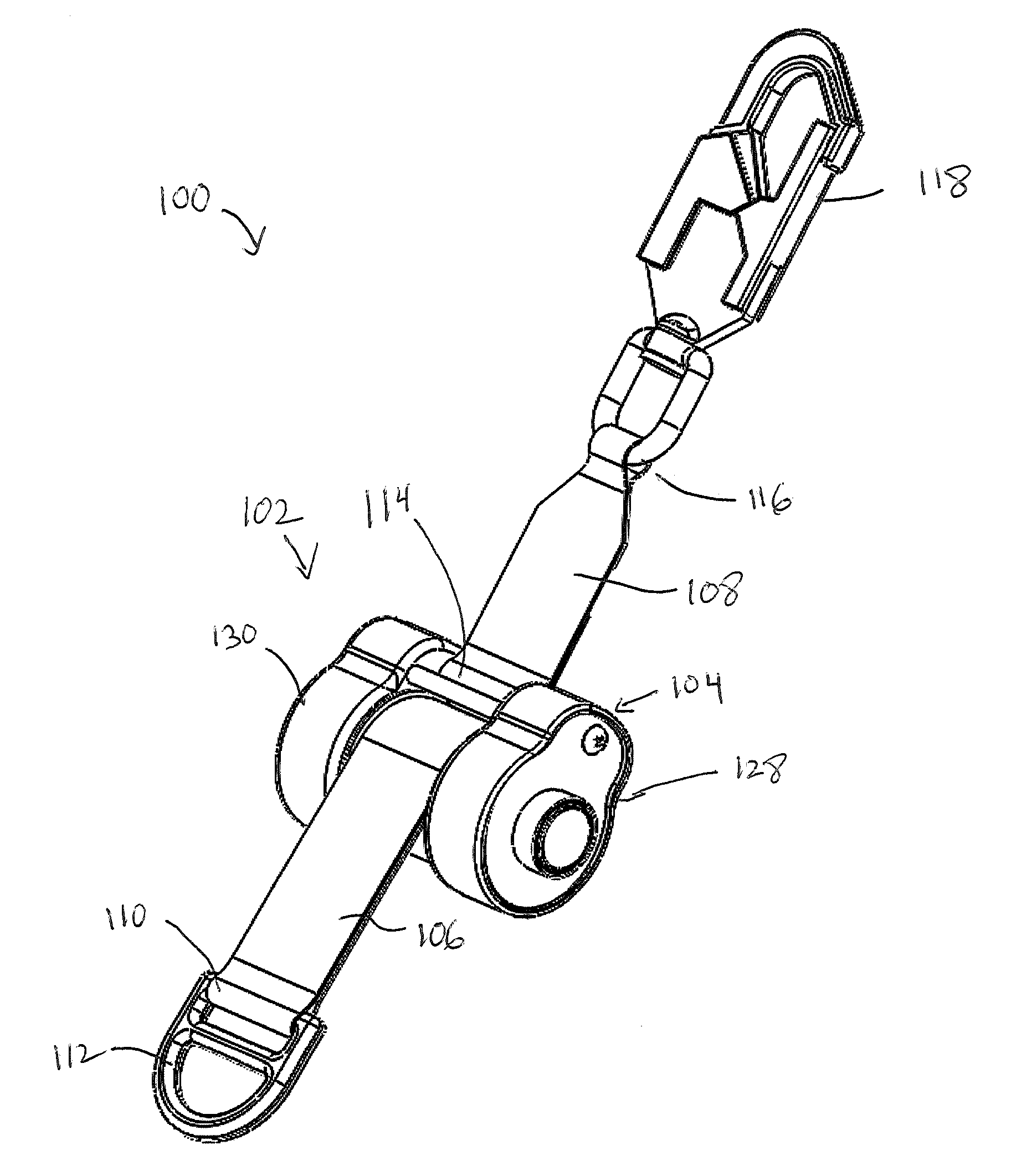
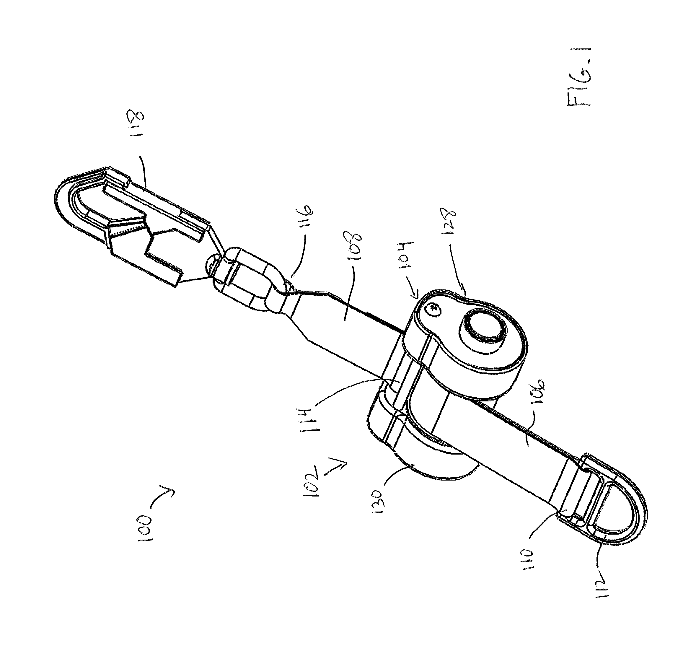
[0025]FIG. 1 shows a perspective view of an exemplary embodiment of a mechanically actuated cargo restraint system 100 for a vehicle, not shown. The vehicle may suitably be an aircraft. The restraint system 100 includes a reel assembly 102 having a frame 104, a first flexible tether 106, and a second flexible tether 108. The first flexible tether 106 is preferably constructed of seat-belt type webbing, and is windable around the rotatable reel assembly 102. The first flexible tether 106 is movable in both a winding direction and an unwinding direction with respect to the frame 104. To this end, the first flexible tether 106 has a first end (not shown in FIG. 1) coupled to the rotatable reel assembly 102.

[0026]The first flexible tether 106 also contains a second end 110 coupled to a rigid anchoring device 112 capable of being coupled to a cargo item. In this embodiment, the cargo item is an aircrew member having a safety attachment with a coupling mechanism, not shown, but which may ...


PUM


Abstract

A mechanically actuated cargo restraint system for a vehicle includes a rotatable reel in a frame, first and second flexible tethers, and a mechanical device. The first flexible tether has a first end coupled to the rotatable reel and a second end capable of being coupled to a cargo item, the first flexible tether is windable around the rotatable reel. The mechanical device includes a pawl and cog that are movable with respect to each other, the pawl coupled to the rotatable reel for rotatable movement therewith. Movement of a cargo item attached to the first flexible tether that causes the first flexible tether to move in an unwinding direction on the rotatable reel causes movement of the pawl-containing member relative to the cog. Velocity in the unwinding direction such as that encountered during a crash or free-fall engages the pawl into the cog, thereby inhibiting movement of the first flexible tether in an unwinding direction on the rotatable reel.

Description

[0001]This application claims the benefit of U.S. Provisional Patent Application Ser. No. 61 / 888,442, filed Oct. 8, 2013.TECHNICAL FIELD OF THE INVENTION[0002]The present invention relates to a restraint system, and more particularly to a reel-based system for restraining cargo, such as personnel in and on moving vehicles.BACKGROUND[0003]Personnel in and on moving vehicles can be subjected to high acceleration environments, such as a crash or quick velocity change that give rise to rapid relative motion between the vehicle and the occupant. These environments create a risk of injury due to contact with vehicle or equipment structures, and a risk of inadvertent ejection from the vehicle. The risk of injury is especially pronounced with personnel who cannot be restrained in a typical seat restraint system due to mobility requirements, such as mobile aircrew members within the cargo bays of military helicopters.[0004]Systems currently in use for restraining helicopter mobile aircrew in...

Claims


Application Information

Patent Timeline
IPC IPC(8): B60P7/08B64D9/00
CPCB60P7/0846B64D9/003B60P7/0853B64D25/06Y02T50/40B65D67/02B65D90/004B65D90/0053B60P7/16B64D9/00B60P7/0823B65D71/02B65D90/006
Inventor TOLLY, AARON JAMESHARRIS, AMY LYNN
Owner WOLF TECHN SERVICES
Why Eureka
Try Eureka