Arrangement for moving a wing tip device between a flight configuration and a ground configuration

a technology of wing tip and flight configuration, which is applied in the field of aircraft, can solve the problems of effectively limited maximum aircraft span and technical challenges, and achieve the effect of reducing the aircraft's span

Inactive Publication Date: 2016-09-01
AIRBUS OPERATIONS LTD
View PDF1 Cites 19 Cited by
  • Summary
  • Abstract
  • Description
  • Claims
  • Application Information

AI Technical Summary

Benefits of technology

[0006]According to a first aspect of the invention, there is provided an aircraft comprising a wing, a wing tip device at the tip of the wing and an actuator, the actuator being arranged to effect movement of the wing tip device between: (i) a flight configuration for use during flight and (ii) a ground configuration for use during ground-based operations, in which ground configuration the wing tip device is moved away from the flight configuration such that the span of the aircraft is reduced, ...

Problems solved by technology

However, the maximum aircraft span is effectively limited by airport operating rules which govern various clearances required when manoeuvring around the airport (such as the span and/or ground clearance required for gate entry and safe taxiway usage).
There are technical challenges in providing a practical arr...

Method used


Image

  • Arrangement for moving a wing tip device between a flight configuration and a ground configuration
  • Arrangement for moving a wing tip device between a flight configuration and a ground configuration
  • Arrangement for moving a wing tip device between a flight configuration and a ground configuration

Examples


first embodiment

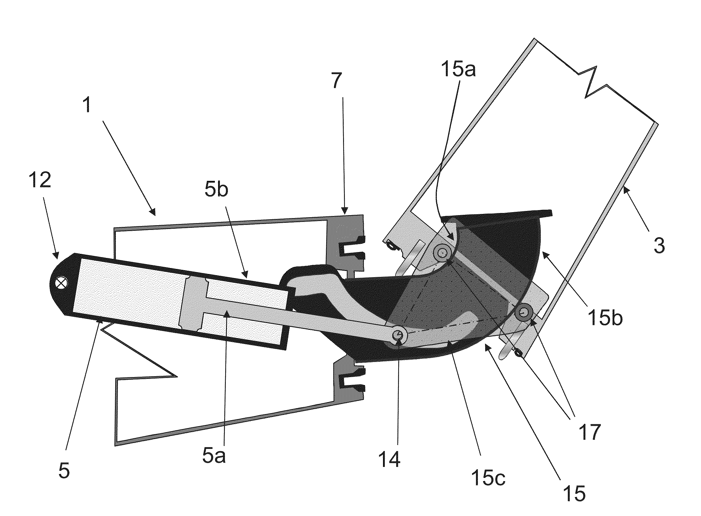
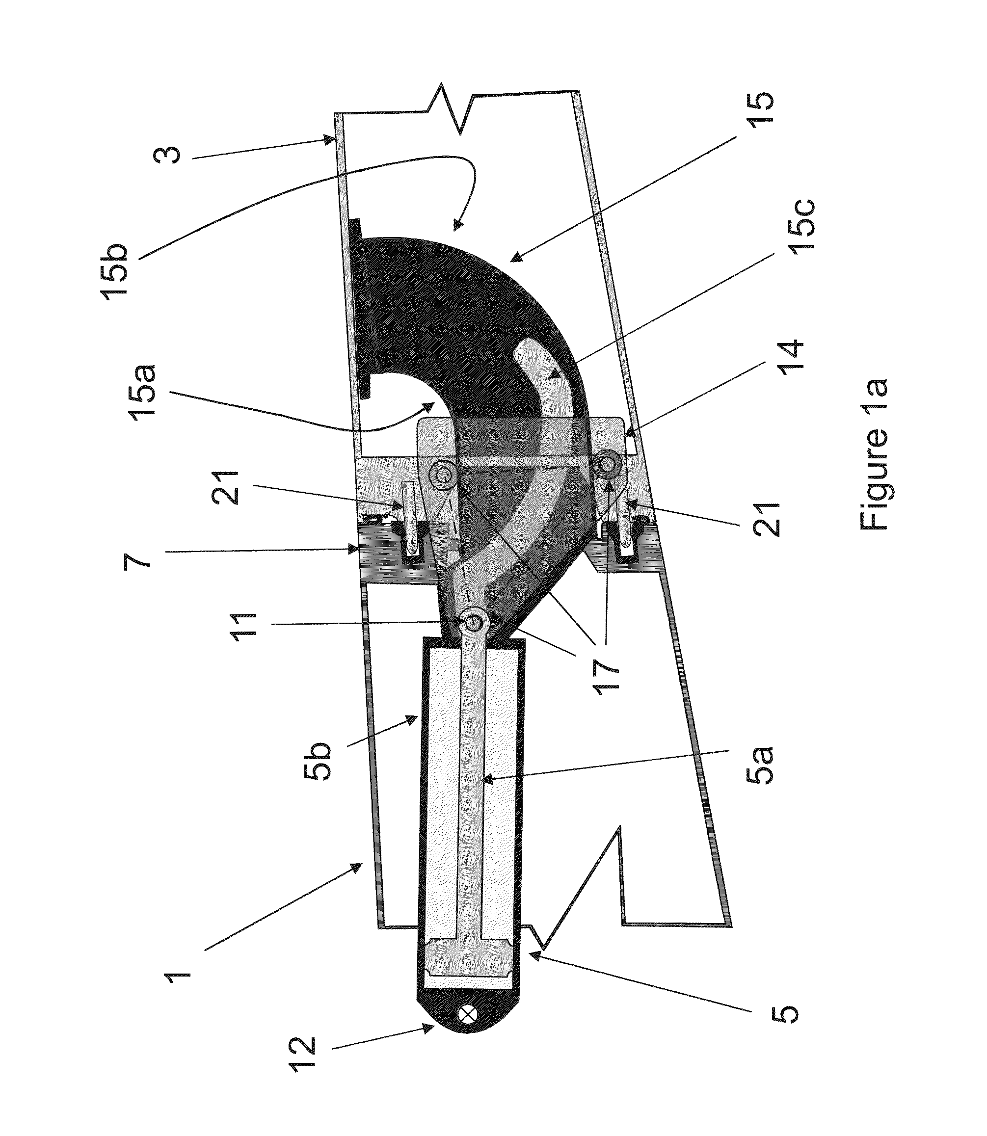
[0030]Figure la shows a schematic side view of a wing 1 and wing tip device 3 according to the invention. The wing tip device 3 is in the form of a planar wing tip extension 3, but for the sake of clarity only the root portion of the wing tip device is shown in FIG. 1a. The wing 1 and wing tip device 3 are on the aircraft 2 shown in FIG. 2.

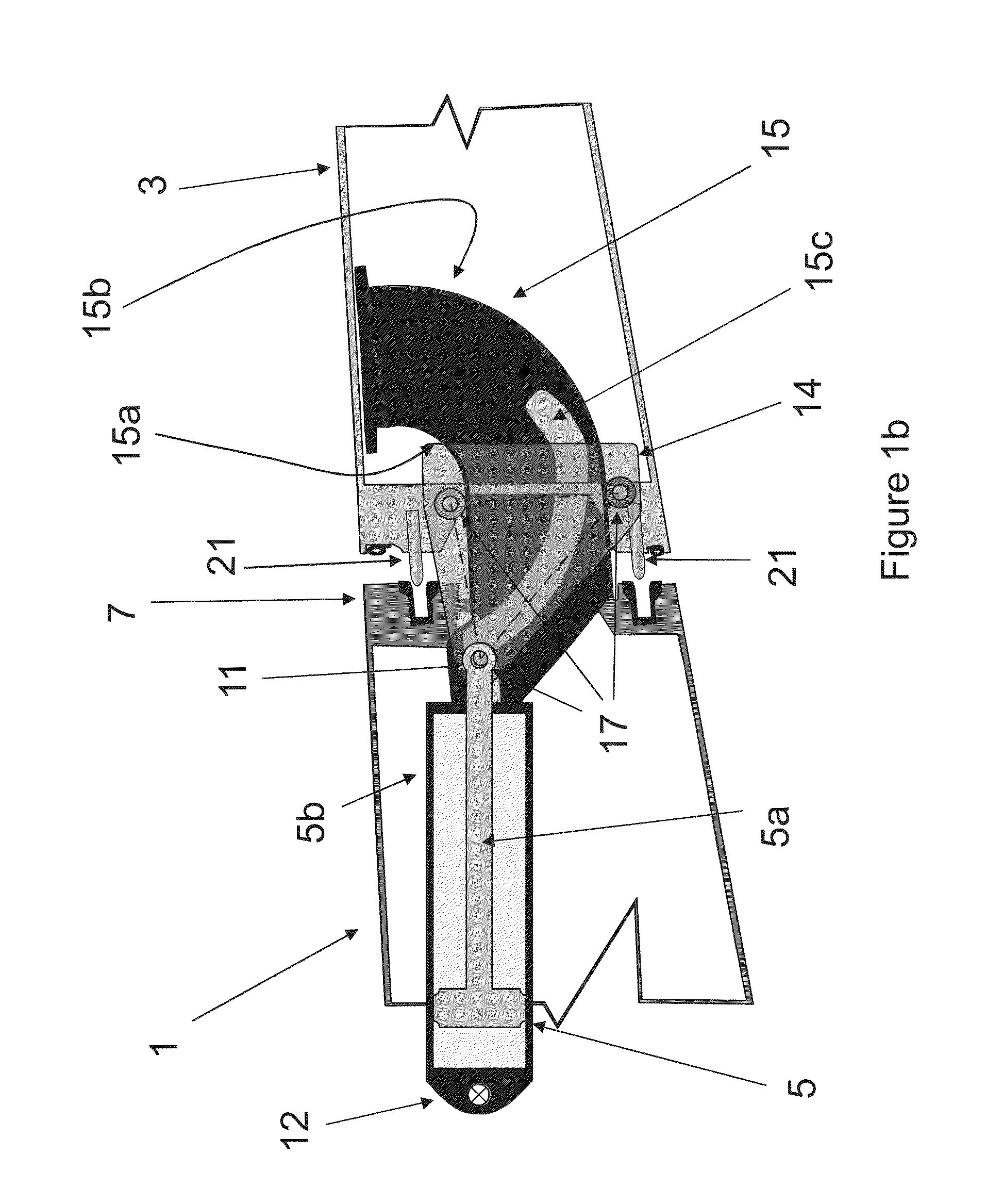
[0031]The wing tip device 3 is moveable from a flight configuration (shown in FIGS. 1a and 2) to a ground configuration (shown in FIG. 1h). In the ground configuration, the wing tip device 3 is moved such that the span of the aircraft is reduced (relative to the flight configuration). This enables the aircraft to have a relatively large span during flight, whilst still complying with airport gate limits, safe taxiway usage etc., on the ground.

[0032]A linear actuator 5 effects movement of the wing tip device between these two configurations. The actuator 5 comprises a piston rod 5a that is extendable / retractable relative to a cylindrical housing 5h...

second embodiment

[0045]FIGS. 3a to 3c show a wing 101 and wing tip device 103 according to the invention, moving from the flight configuration (FIG. 3a) to the ground configuration (FIG. 3c).

[0046]Features in the second embodiment of the invention that correspond to similar features in the first embodiment of the invention, are shown with the same reference numerals as in the first embodiment, but with the addition of the prefix ‘1’ (or ‘10’ where appropriate). For the sake of clarity, the actuator is not shown in FIGS. 3a to 3c. Also, only a selection of the reference numerals are shown.

[0047]The embodiment in FIGS. 3a to 3c is the same as that in FIGS. 1a-1b except for the differences described below.

[0048]Firstly, rather than a planar wing tip extension, the wing tip device 103 of the second embodiment of the invention is an upwardly extending winglet 103. For clarity, only the root portion of the wing tip device 103 is shown in the Figures.

[0049]Secondly, the end rib 107 of the wing 101 is a dif...

third embodiment

[0051]FIG. 4 shows a wing 201 and wing tip device 203 according to the invention, in the flight configuration.

[0052]Features in the second embodiment of the invention that correspond to similar features in the first embodiment of the invention, are shown with the same reference numerals as in the first embodiment, but with the addition of the prefix ‘2’ (or ‘20’ where appropriate). For the sake of clarity, only a selection of the reference numerals are shown in FIG. 4.

[0053]The embodiment in FIG. 4 is the same as that in FIGS. 1a-1h except that the slot 15c is replaced with a rail 215c for forming the third guide surface. To ensure the carriage 214 follows the shape of the rail 215, the contact 217 for moving along the third guide surface 215c comprises two wheels located either side of the rail 215c. The lower wheel is biased into position against the rail 215c by a spring 227 attached to a finger 229 on the end of the actuator rod 205a.

[0054]Whilst the present invention has been ...


PUM


Abstract

An aircraft comprises a wing, a wing tip device at the tip of the wing and an actuator. The actuator is arranged to effect movement of the wing tip device between a flight configuration for use during flight and a ground configuration in which the wing tip device is moved away from the flight configuration such that the span of the aircraft is reduced. The aircraft comprises a carriage guide, such as a rail, fixed relative to the wing, and a carriage arranged to move along the carriage guide as the wing tip device moves between the flight and ground configurations. The wing tip device is fixed relative to the carriage such that the path of the wing tip device, during movement of the wing tip device, between the flight and the ground configurations, is defined by the shape of the carriage guide.

Description

BACKGROUND OF THE INVENTION[0001]The present invention relates to aircraft and more specifically, but not exclusively, to passenger aircraft with wing tip devices.[0002]There is a trend towards increasingly large passenger aircraft, for which it is desirable to have correspondingly large wing spans. However, the maximum aircraft span is effectively limited by airport operating rules which govern various clearances required when manoeuvring around the airport (such as the span and / or ground clearance required for gate entry and safe taxiway usage).[0003]In some suggested designs, aircraft are provided with wing tip devices which may be folded to reduce the span of the aircraft on the ground (compared to when the aircraft is configured for flight). The wing tip devices may, for example, be configurable between: (i) a flight configuration for use during flight and (ii) a ground configuration for use during ground-based operations, in which ground configuration the wing tip device is mo...

Claims


Application Information

Patent Timeline
IPC IPC(8): B64C23/06
CPCB64C23/065B64C3/56B64C23/072Y02T50/10B64C3/546B64C3/58
Inventor THOMPSON, ROBERT IANLIVINGS, NICK
Owner AIRBUS OPERATIONS LTD
Why Eureka
Try Eureka