Fluorescent tube attaching structure

a technology of fluorescent tubes and fixing structures, which is applied in the direction of coupling device connections, instruments, lighting support devices, etc., can solve the problems of troublesome soldering, poor sealing effect, and inability to prevent the positional deviation between the fluorescent tube and the holder

Inactive Publication Date: 2010-04-20
JST MFG CO LTD
View PDF34 Cites 11 Cited by
  • Summary
  • Abstract
  • Description
  • Claims
  • Application Information

AI Technical Summary

Benefits of technology

[0012]According to this mode, between the contact portions of the straight portions of the pair of elastic pieces, the terminal of the fluorescent tube is elastically clamped. As a result, the contact portions come into contact with the terminal with a predetermined contact pressure, so that the contact and the terminal can be reliably electrically connected to each other.
[0013]In addition, by a simple operation of inserting the terminal of the fluorescent tube between the pair of straight portions extending along the fluorescent tube attaching direction, the contact and the terminal can be readily electrically connected to each other.
[0014]Furthermore, the intermediate portion of the fluorescent tube in the longitudinal direction is supported by the holder, so that the load applied to the terminal of the end portion of the fluorescent tube can be reduced in comparison with the case of supporting only both ends of the fluorescent tube. In addition, the span for supporting the fluorescent tube can be stably reduced, and as a result, the fluorescent tube can be supported steadly. Therefore, the fluorescent tube does not vibrate.
[0015]In addition, the pair of straight portions extend along the fluorescent tube attaching direction, and this provides the following advantage. That is, even if the holder and the fluorescent tube have variations in dimensional errors, the position of the terminal of the fluorescent tube in the attaching direction can be adjusted without applying an excessive force to the terminal of the fluorescent tube, by shifting the position of the terminal of the florescent tube along the straight: portions. Thereby, the variations in dimensional errors are absorbed. The positional deviation between the fluorescent tube and the holder can be prevented as much as possible, and the fluorescent tube can be reliably held by the holder.

Problems solved by technology

However, in the documents 1 and 2, there is a risk that conducting failure may occur between the terminal and the connection fitting due to defective soldering.
In addition, the soldering is troublesome.
Therefore, great labor is required for soldering.
Not only the case of the cold cathode fluorescent tube, but also cases using other fluorescent tubes such as an external electrode fluorescent tube have a similar problem.

Method used


Image

  • Fluorescent tube attaching structure
  • Fluorescent tube attaching structure
  • Fluorescent tube attaching structure

Examples


Embodiment Construction

[0032]A preferred embodiment of the present invention will be described with reference to the accompanying drawings.

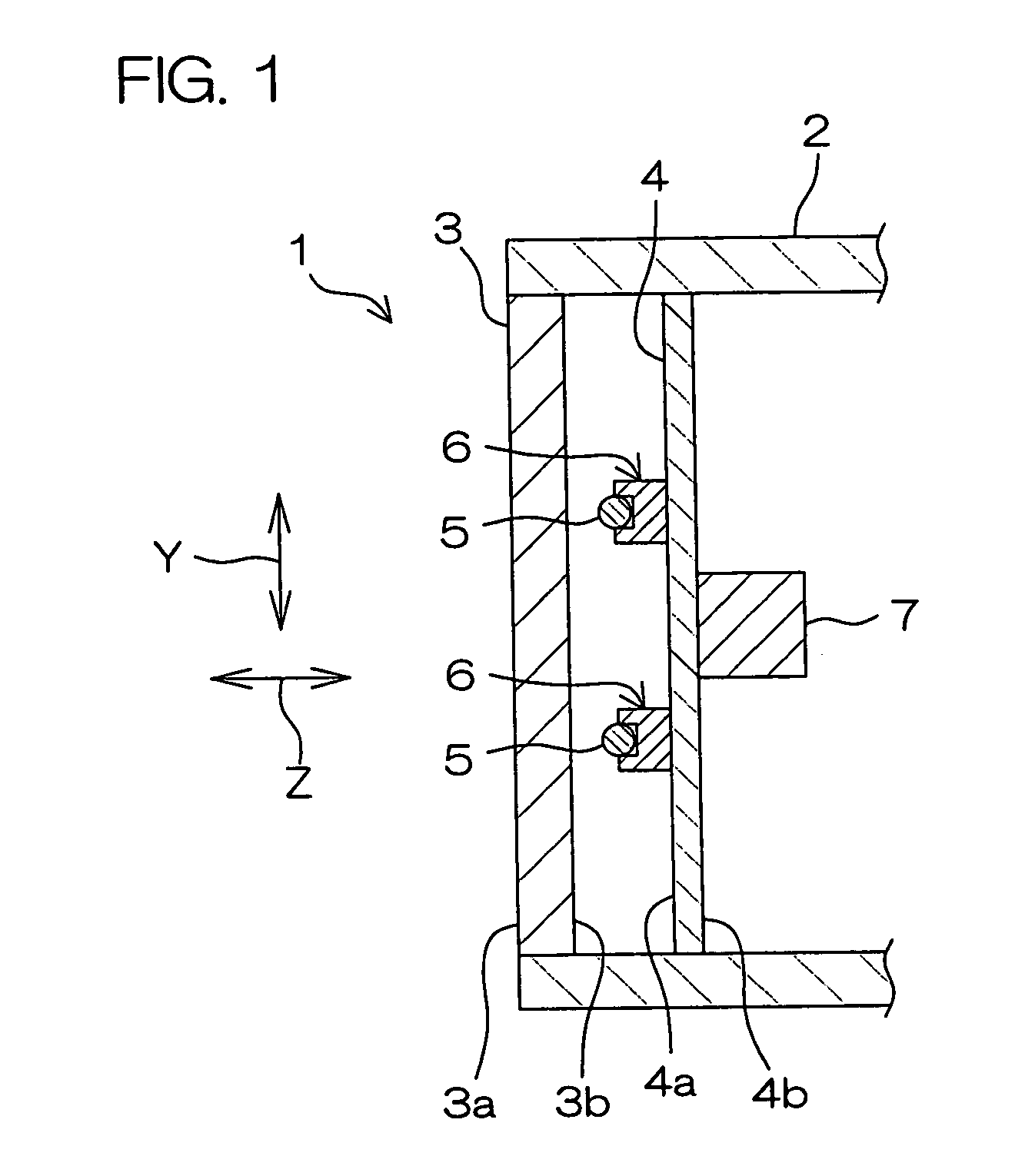
[0033]FIG. 1 is a schematic sectional view showing a general construction of a liquid crystal display device having a fluorescent tube attaching structure according to an embodiment of the present invention. Referring to FIG. 1, the liquid crystal display device 1 is used as, for example, a monitor of a television or a personal computer.

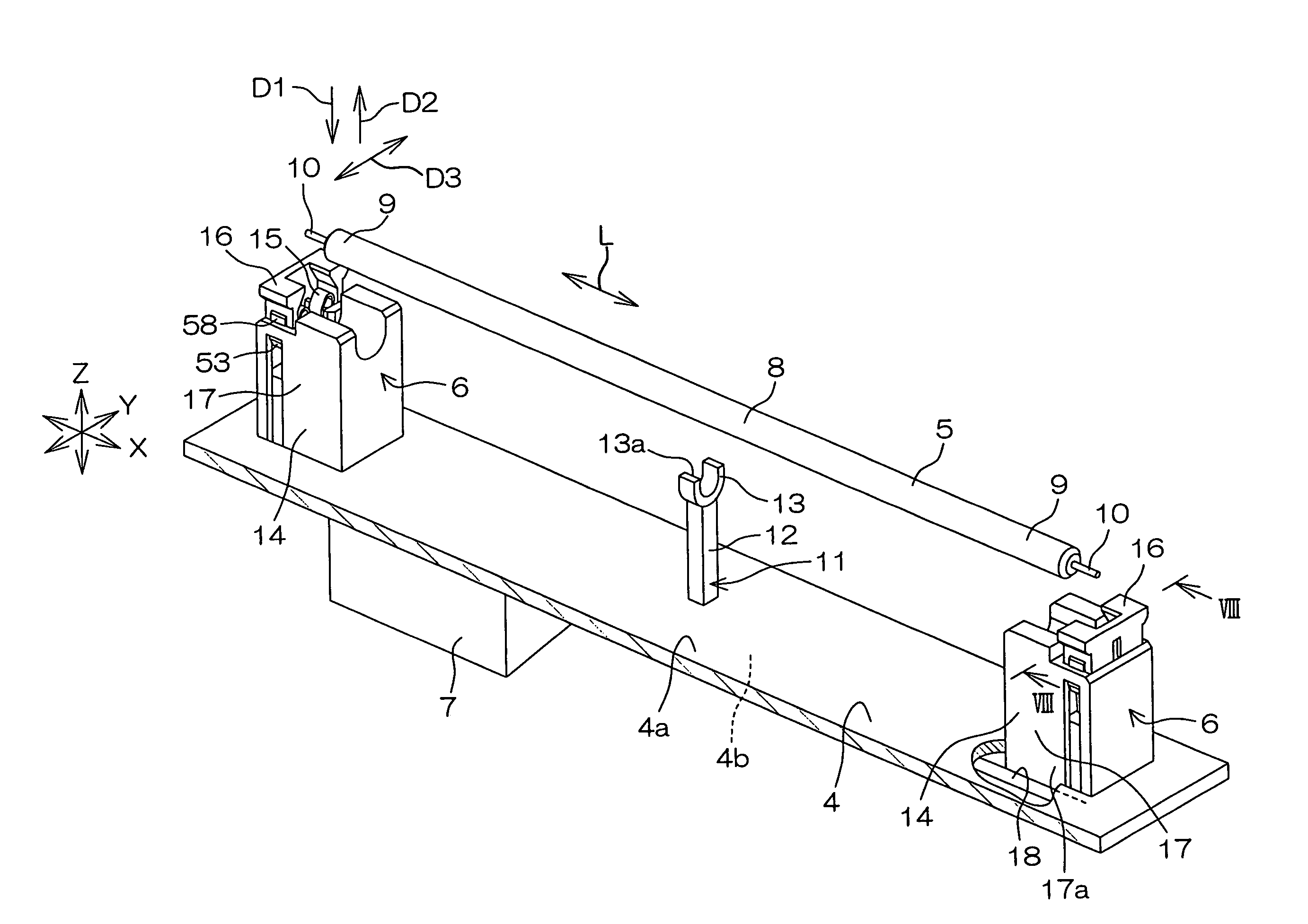
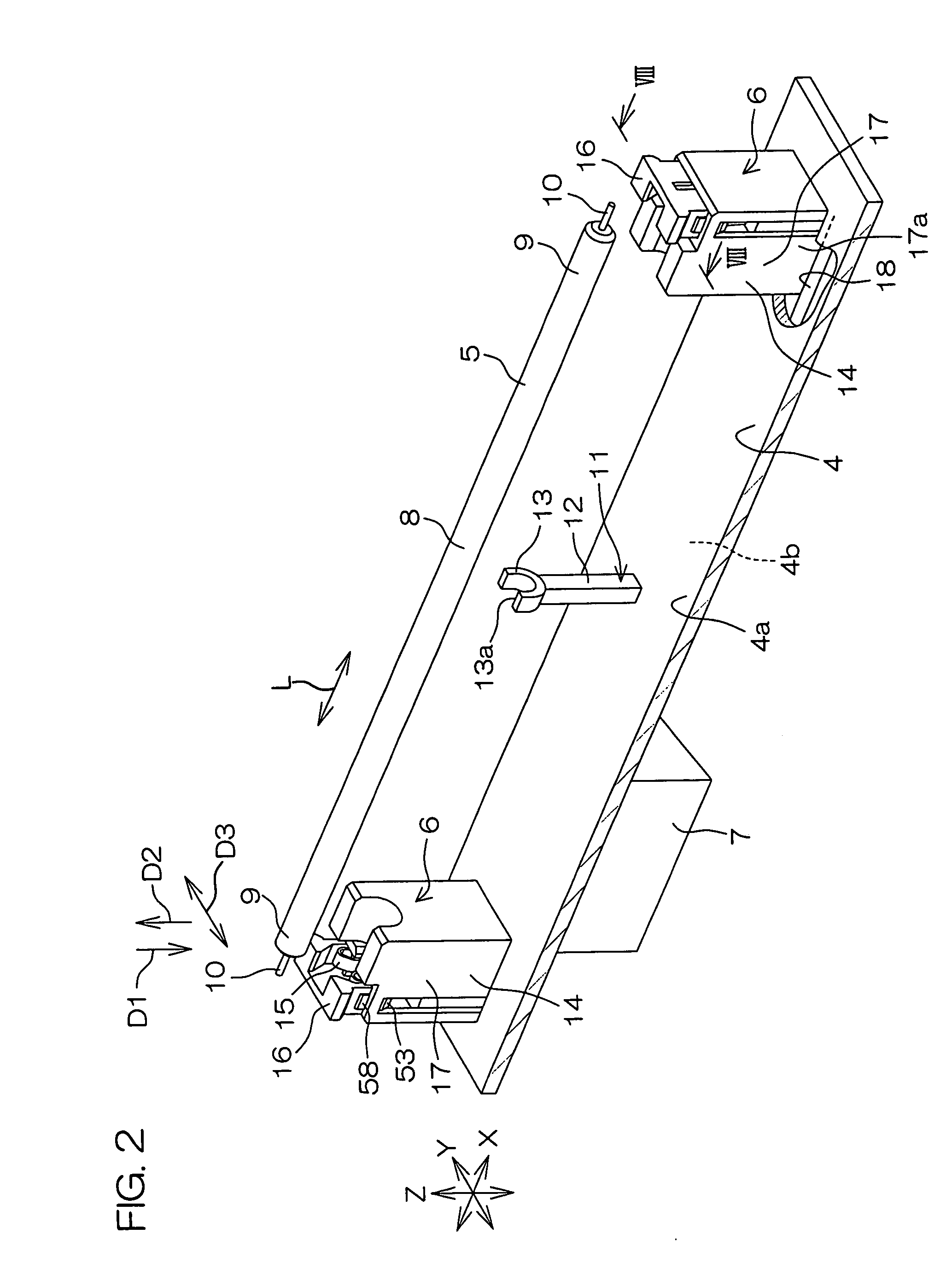
[0034]The liquid crystal display device 1 includes a casing 2, a liquid crystal panel 3, a circuit board 4 disposed in the rear of the liquid crystal panel 3, a plurality of cold cathode fluorescent tubes 5 as fluorescent tubes, electrical connectors 6 (hereinafter, also referred to as connectors, simply), and an inverter circuit 7.

[0035]The liquid crystal panel 3 is a non light-emitting display panel, and is attached to an opening on the front of the casing 2. A front face 3a of the liquid crystal panel 3 faces forward from the casing ...


PUM


Abstract

A structure for attaching a fluorescent tube includes a base, a holder supported by the base, and a pair of contacts. The holder holds an intermediate portion of the fluorescent tube while restraining the fluorescent tube from moving in a radial direction. To the pair of contacts, terminals of a pair of end portions of the fluorescent tube are respectively attachable in an attaching direction corresponding to the radial direction of the fluorescent tube. Each contact includes a pair of elastic pieces facing each other. The pair of elastic pieces have a pair of straight portions extending substantially straight along the attaching direction and facing each other. On the pair of straight portions, a pair of contact portions for clamping the corresponding terminal of the fluorescent tube therebetween are formed.

Description

BACKGROUND OF THE INVENTION[0001]1. Field of the Invention[0002]The present invention relates to a attaching structure for a long fluorescent tube.[0003]2. Description of Related Arts[0004]For example, as connecting structures for terminals of fluorescent tubes such as cold cathode fluorescent tubes to be used as a backlight of a liquid crystal display type television or monitor, the following documents 1 and 2 have been proposed.[0005]Document 1: Japanese Unexamined Patent Publication No. 2001-250605 (Date of publication: Sep. 14, 2001)[0006]Document 2: Japanese Unexamined Patent Publication No. 2004-259645 (Date of publication: Sep. 16, 2004)[0007]In the documents 1 and 2, a connection fitting fixed to one end of an electric wire is soldered to a terminal (electrode) of a cold cathode fluorescent tube. The other end of the electric wire is connected to an inverter circuit via a connector. Electrical power from the inverter circuit is supplied to the cold cathode fluorescent tube v...

Claims


Application Information

Patent Timeline
Patent Type & Authority Patents(United States)
IPC IPC(8): F21V21/00F21S4/00H01R13/15H01R33/02
CPCH01R33/0827H01R33/7692G02F1/1335F21V19/00H01J61/78
Inventor MIYAZONO, KATSUNORI
Owner JST MFG CO LTD
Why Eureka
Try Eureka