Hall effect ringlike ion thruster

An ion thruster and Hall effect technology, applied in thrust reversers, using plasma, machines/engines, etc., can solve the problems of difficult discharge and uneven particle distribution, saving installation space, improving ionization rate, increasing Effect of input power and upper limit on plasma density

Active Publication Date: 2020-10-30
DALIAN UNIV OF TECH
View PDF5 Cites 10 Cited by
  • Summary
  • Abstract
  • Description
  • Claims
  • Application Information

AI Technical Summary

Problems solved by technology

[0003] However, the existing ring-type ion thrusters still have problems such as difficult discharge and uneven distribution of particles in the discharge chamber.

Method used


Image

  • Hall effect ringlike ion thruster
  • Hall effect ringlike ion thruster

Examples


Embodiment Construction

[0025] In order to make the purpose, features and advantages of the present invention more obvious and understandable, the present invention will be further described below with reference to the accompanying drawings and in conjunction with specific embodiments, so that those skilled in the art can implement it with reference to the description. The scope of protection is not limited to this specific embodiment. Apparently, the embodiments described below are only some, not all, embodiments of the present invention. Based on the embodiments of the present invention, all other embodiments obtained by persons of ordinary skill in the art without making creative efforts belong to the protection scope of the present invention.

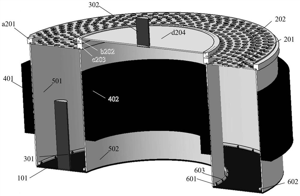
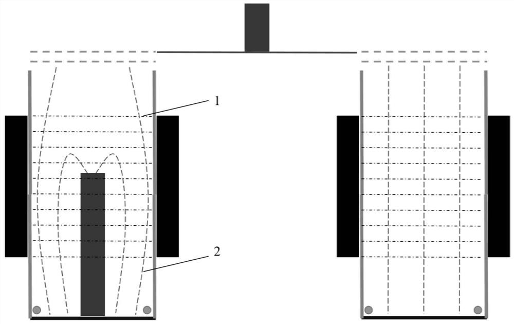
[0026] Such as figure 1 , figure 2 A Hall-effect annular ion thruster shown includes a bottom anode 101, an annular grid, an annular permanent magnet, an insulating sleeve, a working fluid distributor group, a bias discharge cathode 301, and a neutraliz...


PUM


Abstract

The invention discloses a Hall effect ringlike ion thruster and belongs to the technical field of ion thrusters. The ringlike ion thruster comprises a bottom positive pole, a ringlike grid electrode,ringlike permanent magnets, insulating sleeves, a working medium distributor set, a bias discharging negative pole and a neutralizer. Working medium gas enters a discharging chamber through bottom working medium distributors. Nozzles of the working medium distributors are oriented along the wall face so that the gas can be more uniform in a cavity. An axial electric field is formed among the positive pole, the negative pole and the grid electrode. A radial magnetic field is formed by the inner ringlike permanent magnet and the outer ringlike permanent magnet, and an E*B orthogonal field is formed by the radial magnetic field and the axial electric field. Electrons sprayed out of the negative pole are subjected to Hall drift under the effect of the orthogonal field, and the working medium gas is ionized to generate plasmas. Then, the plasmas are extracted and accelerated by the ringlike grid electrode and neutralized by electrons emitted by the neutralizer to generate thrust. The ionization rate and input power of the thrust generated by the Hall effect ringlike ion thruster are far higher than those of a traditional ion thruster, and performance of the ion thruster can be remarkably improved.

Description

technical field [0001] The invention belongs to the technical field of ion thrusters, and more specifically relates to a Hall effect ring type ion thruster. Background technique [0002] The working process of the ion thruster is roughly divided into three stages: 1) The propellant is ionized in the discharge chamber to generate ions; 2) The ions are accelerated by the grid system to form a beam; 3) The beam is neutralized by the neutralizer to form a plume flow. Among them, the stage where ions are accelerated by the grid system is the main stage for obtaining thrust and output power. This makes the thrust and power level of the ion thruster closely related to the size of the grid, and increasing the size of the grid is the key to greatly improving the thrust and power level of the ion thruster. The discharge chamber of the ring-type ion thruster is composed of two anode sleeves, and the overall shape is ring-shaped. However, since the cathode is biased to one side of the...

Claims


Application Information

Patent Timeline
Patent Type & Authority Applications(China)
IPC IPC(8): F03H1/00
CPCF03H1/0075
Inventor 鹿畅夏广庆孙斌韩亚杰
Owner DALIAN UNIV OF TECH
Why Eureka
Try Eureka