Thrust balancing device for cryogenic fluid machinery

Inactive Publication Date: 2009-03-19
ELLIOTT CO
View PDF13 Cites 11 Cited by
  • Summary
  • Abstract
  • Description
  • Claims
  • Application Information

AI Technical Summary

Benefits of technology

[0007]An object of this invention is to provide a way for the lower bearing to be disposed closer to the upper beari

Problems solved by technology

As the generator is the dominant component in terms of rotordynamic stability, the increased size has negative ramifications to the machine reliability.
For example, higher power ratings of variable speed hydraulic turbine generators implicitly require larger physical sizes, but the possible loss of generator load demands critical speed separation below continuous speed and above maximum “breakaway” speed.
Furthermore, in the design of cryogenic turbine generators and pumps, there limitations on bearing size, shaft diame

Method used


Image

  • Thrust balancing device for cryogenic fluid machinery
  • Thrust balancing device for cryogenic fluid machinery
  • Thrust balancing device for cryogenic fluid machinery

Examples


Embodiment Construction

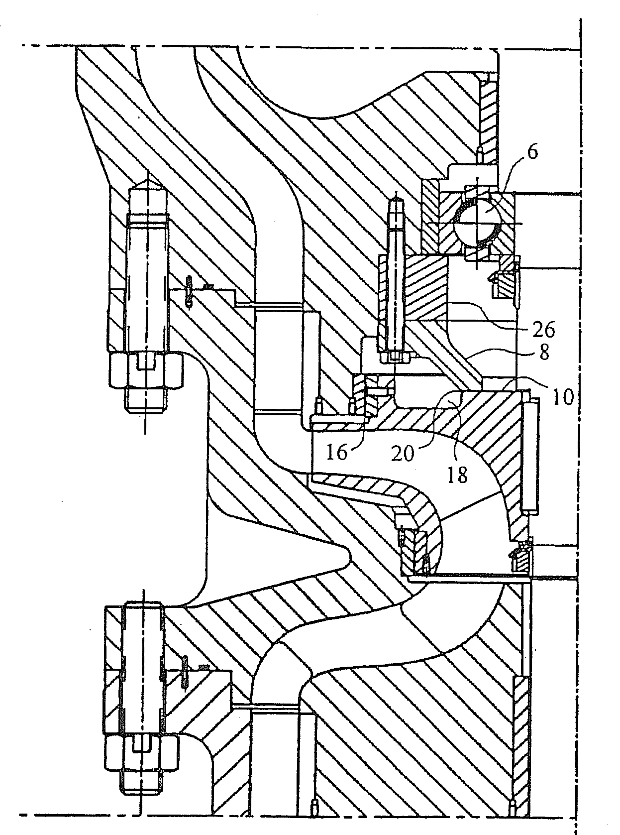
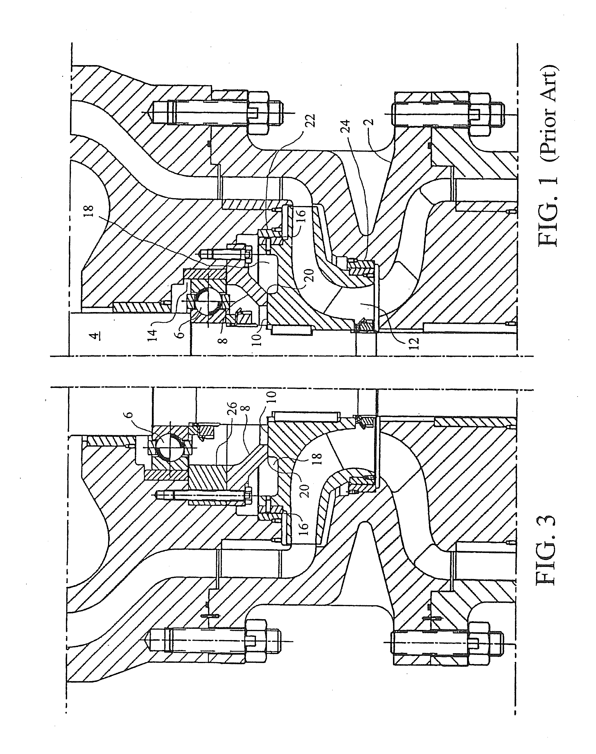
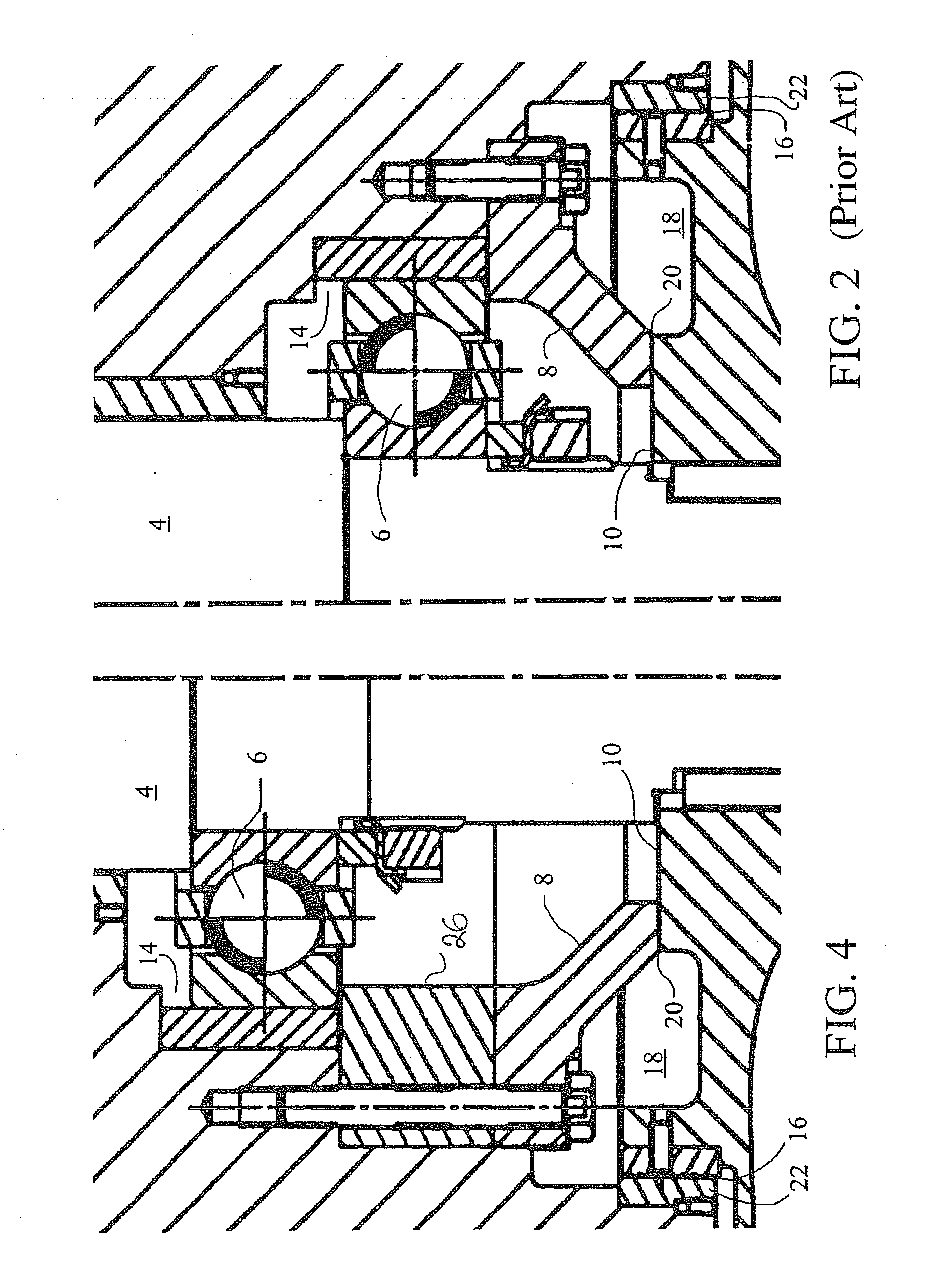
[0014]Referring to FIGS. 1 and 2, a prior art machine with a conventional thrust equalizing mechanism is illustrated to have a housing 2, a shaft 4, a lower bearing 6, a stationary thrust plate 8, a throttle ring 10 affixed to the shaft, a runner 12, a gap 14 above the lower bearing which allows the shaft (and the bearing and throttle ring) to rise in response to any unbalance thrust from below, a fixed orifice 16 which communicates product fluid to a chamber 18 disposed above the throttle ring, a variable orifice 20 defined between thrust plate and the throttle ring, an upper wearing ring 22, and a lower wearing ring 24. The operation of the thrust equalizing mechanism is simple. The upper wearing ring 22 is larger in diameter than the lower wearing ring 24 resulting in a net resultant force in the upper direction. Due to this upward force, the shaft 4, and all its rotating components move upward, the upward movement of the throttle ring 10 reducing the variable orifice 20 between ...


PUM


Abstract

An improvement for a turbine generator or pump having main bearings separated by a span of shaft and a thrust equalizing mechanism adjacent one of said main bearings, the improvement comprising a stationary length compensator interposed between the thrust equalizing mechanism and its adjacent main bearing to reduce the span between said main bearings. Preferably the length compensator is composed of material that shrinks less than the shaft of the generator, and the height of the length compensator, i.e., the compensating dimension, is selected according to desired thrust equalizing mechanism operating parameters over a temperature range.

Description

[0001]Applicant claims the benefit of U.S. Provisional Application No. 60 / 446,460, filed Feb. 10, 2003.BACKGROUND OF THE INVENTION[0002]This invention relates in general to means and methods for balancing the thrust felt by pumps and turbine generators operating in a cryogenic environment, and in particular to a novel improvement in a thrust balancing configuration to enhance the rotordynamic behavior of vertical cryogenic pumps and turbine generators.[0003]The LNG (liquid nitrogen gas) production plants currently in the design stages are utilizing economy of scale to increase production with lower capital costs, which has the effect of increasing the power ratings of the critical rotating equipment being supplied.[0004]As the power requirements increase with the demand for the next generation of liquefaction plants, the generator size must increase physically. As the generator is the dominant component in terms of rotordynamic stability, the increased size has negative ramification...

Claims


Application Information

Patent Timeline
IPC IPC(8): F01D3/00F01D25/16
CPCF01D25/16F16C19/52F05D2300/50212F05D2230/642F16C41/02
Inventor MADISON, JOEL V.
Owner ELLIOTT CO
Why Eureka
Try Eureka