Steel-concrete composite tunnel lining supporting structure and manufacturing and construction method thereof

A supporting structure and concrete technology, applied in tunnel lining, tunnel, wellbore lining, etc., can solve the problems that the supporting strength cannot be strictly guaranteed, affect the progress of the project, and require large equipment investment, so as to save the back grouting process. , The effect of saving engineering volume and reducing equipment investment

Active Publication Date: 2015-12-02
NANJING LIANZHONG CONSTR ENG TECH
View PDF5 Cites 10 Cited by
  • Summary
  • Abstract
  • Description
  • Claims
  • Application Information

AI Technical Summary

Problems solved by technology

The above-mentioned structure and construction method have the following problems: ① Generally speaking, the primary support layer (i.e. the primary lining layer) of the tunnel bears most of the load on the upper part of the cave, but the bearing capacity of the primary support layer depends not only on the inner steel arch The frame also depends on the cooperation and support of the concrete, and the concrete will not immediately play a load-bearing role when it is poured. It needs solidification and hardening time. During this period of time, the support strength cannot be strictly guaranteed, especially in the crust. Co

Method used


Image

  • Steel-concrete composite tunnel lining supporting structure and manufacturing and construction method thereof
  • Steel-concrete composite tunnel lining supporting structure and manufacturing and construction method thereof
  • Steel-concrete composite tunnel lining supporting structure and manufacturing and construction method thereof

Examples


Embodiment Construction

[0066] The technical solution of the present invention will be further described below in conjunction with the accompanying drawings.

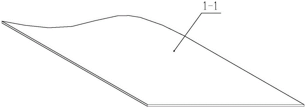
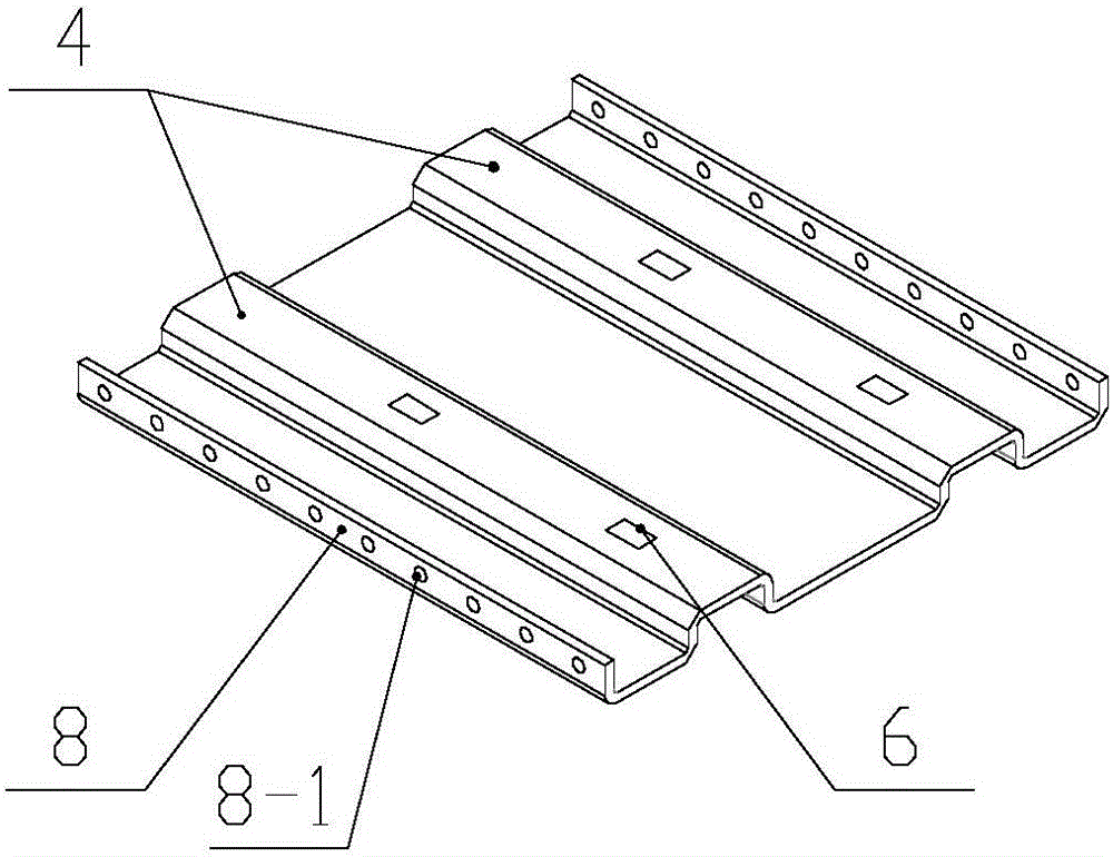
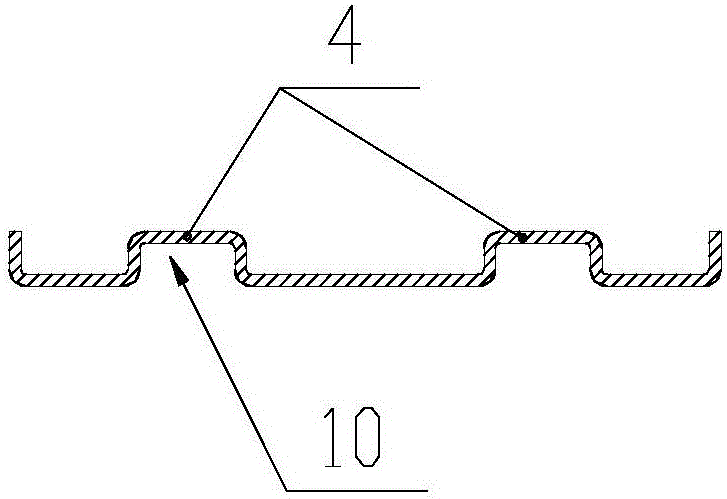
[0067] The first tunnel lining support structure of the present invention is formed by assembling curved unit plates 1 along the circumferential and axial directions of the tunnel wall; when assembled in the circumferential direction, adjacent unit plates 1 pass through side flanges 9 Connection, adjacent unit plates 1 are connected through end face flanges 8 during axial assembly. Since the unit plate 1 has a certain curvature, it has a pair of arc-shaped sides 2 and a pair of straight sides 3, and along the direction of the straight sides 3, ribs 4 are arranged at intervals on the inner wall of the unit plate 1 (that is, inside the arc), The number of ribs 4 is determined according to the actual situation. The radian of the ribs 4 is consistent with that of the arc-shaped side 2, or close to the arc-shaped side. A cavity cylinder 5 is formed...


PUM


Abstract

The invention discloses a steel-concrete composite tunnel lining supporting structure and a manufacturing and construction method thereof. The supporting structure is formed by splicing unit plate pieces with radian in the circumferential direction and axial direction of a tunnel wall. Each unit plate piece is provided with a pair of arc edges and a pair of straight edges. The inner wall of each unit plate piece is provided with protruding ribs at intervals in the straight edge direction. The radian of the protruding ribs is consistent with that of the arc edges, and cavity pillars are formed between the protruding ribs and the unit plate pieces. The surfaces of the protruding ribs are provided with concrete pouring holes, and unit plate pieces corresponding to the protruding ribs are provided with concrete overflowing holes. Meanwhile, the arc edges are inwards bent to form end face flanges, and the straight edges are provided with side edge flanges. The steel-concrete composite tunnel lining supporting structure has the advantages that the supporting structure can bear pressure load of the upper portion of a tunnel and the surrounding rock immediately, and the newly dug tunnel can be supported rapidly and timely and is prevented from collapsing; the supporting structure can be used for the primary lining as well as integrating the primary lining and the secondary lining and an also be used for repairing, reinforcing and the like of crippled tunnels.

Description

technical field [0001] The invention relates to a tunnel lining support structure, in particular to a steel-concrete composite structure for the inner lining of highway, railway, water transfer or air defense engineering tunnels and its manufacturing and construction methods. Background technique [0002] Tunnel lining is a permanent support structure built with steel arch frames and steel-concrete materials along the upper circumferential arch wall of the tunnel body to prevent the surrounding rock in the tunnel from deformation or collapse. The existing tunnel lining is generally provided with a primary support layer and a secondary lining layer. The primary support layer structure is composed of I-beams, arch frames, steel mesh, anchor rods and shotcrete, which are used to withstand the pressure generated by the plastic deformation of the structure above the cavern after tunnel excavation and prevent the surrounding rock from deforming or collapsing. After setting up the...

Claims


Application Information

Patent Timeline
IPC IPC(8): E21D11/10E21D11/18
CPCE21D11/14
Inventor 战福军
Owner NANJING LIANZHONG CONSTR ENG TECH
Why Eureka
Try Eureka