Hybrid wireless power transmitting system and method therefor

Active Publication Date: 2016-09-01
GE HYBRID TECH
View PDF4 Cites 49 Cited by
  • Summary
  • Abstract
  • Description
  • Claims
  • Application Information

AI Technical Summary

Benefits of technology

[0069]According to one embodiment of the present invention above, by checking the type of a wireless power receiving apparatus through an antenna and a transmitting coil and accordingly transmitting a wireless power signal based on an appropriate scheme, an inductive wireless power receiving apparatus and a resonant wireless power receiving apparatus can be charged.
[0070]Also, in case a wireless power receiving apparatus is a hybrid type, a wireless power signal with more improved transmission efficiency can be transmitted.
[0071]Also, since the type of a wireless power receiving apparatus can be checked without using a separate communication unit or detection sensor, the number of components can be reduced, and manufacturing costs can be reduced.
[0

Problems solved by technology

However, most of communication information devices still rely on batteries, and use of the devices is being limited since they receive power via power lines.
Therefore, the wireless information network environment cannot be fully utilized unless the problem related to device power is solved.
The microwave receiving method has an advantage that power can be transmitted a long distance since microwaves can be radiated into the air through an antenna, but efficiency of power transmission is restricted

Method used


Image

  • Hybrid wireless power transmitting system and method therefor
  • Hybrid wireless power transmitting system and method therefor
  • Hybrid wireless power transmitting system and method therefor

Examples


first embodiment

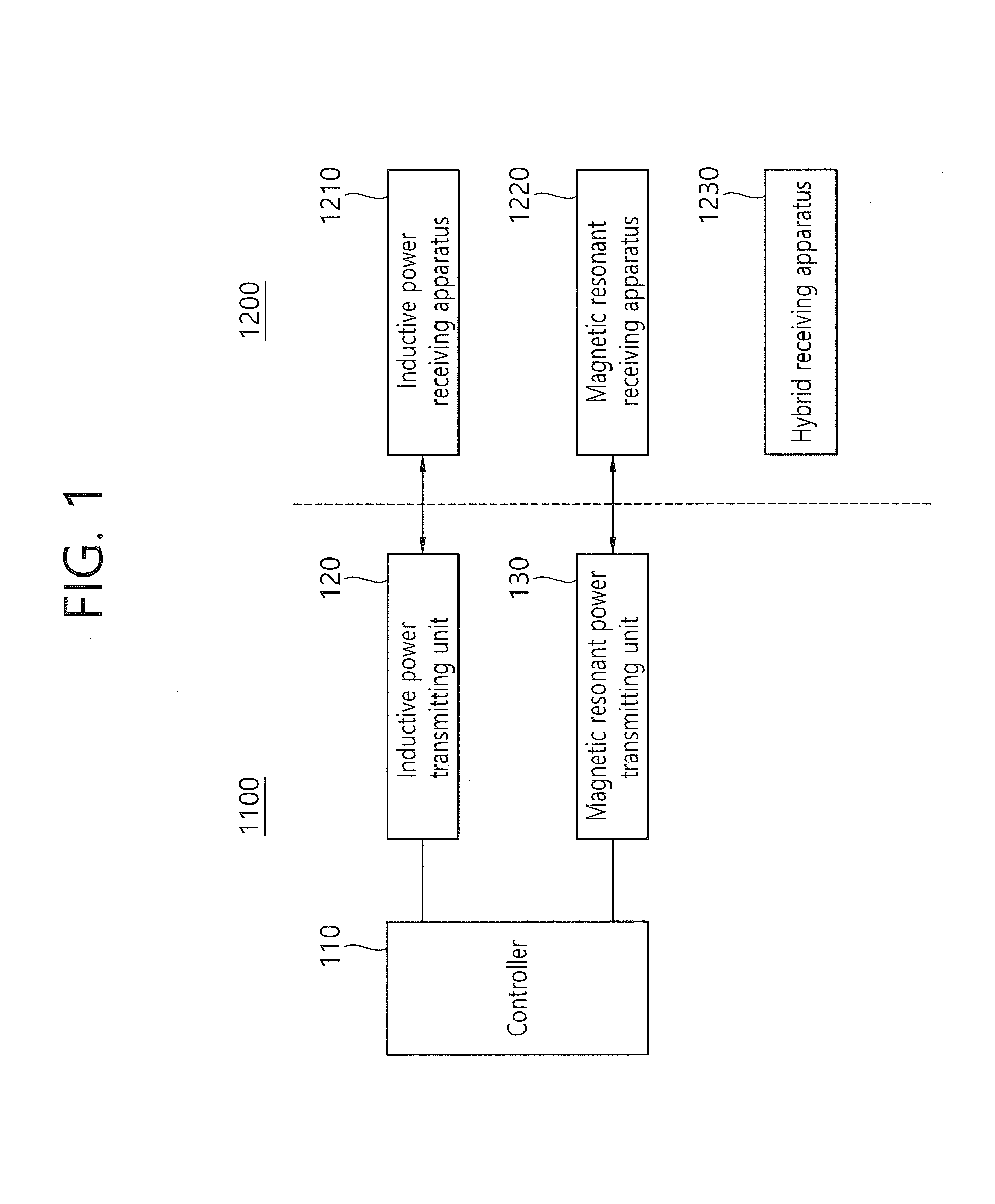
[0105]FIG. 1 illustrates a block diagram of a wireless power transmitting system including a hybrid wireless power transmitting apparatus according to a first embodiment of the present invention.

[0106]As shown in the figure, a wireless power system according to the present invention comprises a wireless power transmitting apparatus 1100 and a wireless power receiving apparatus 1200.

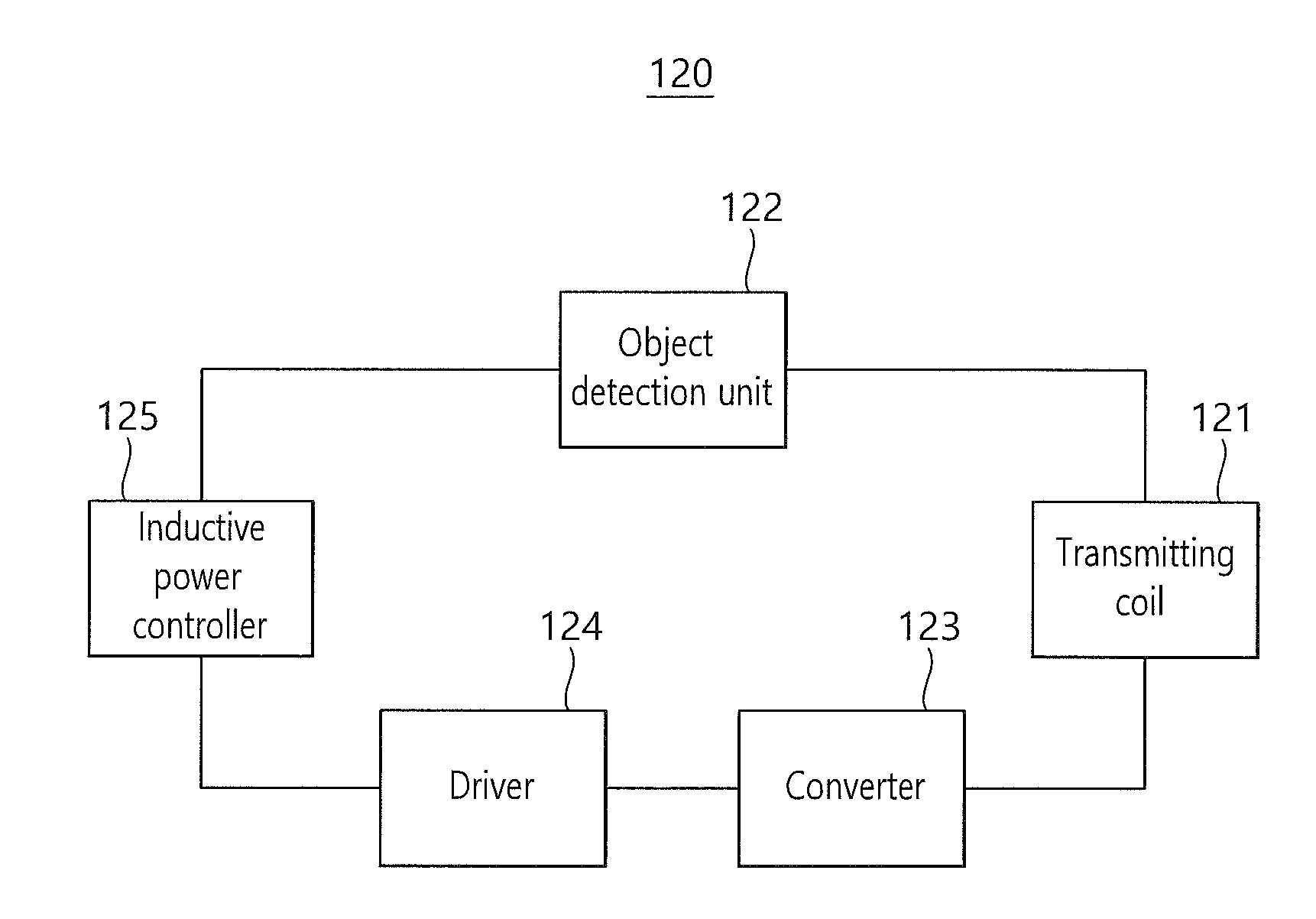
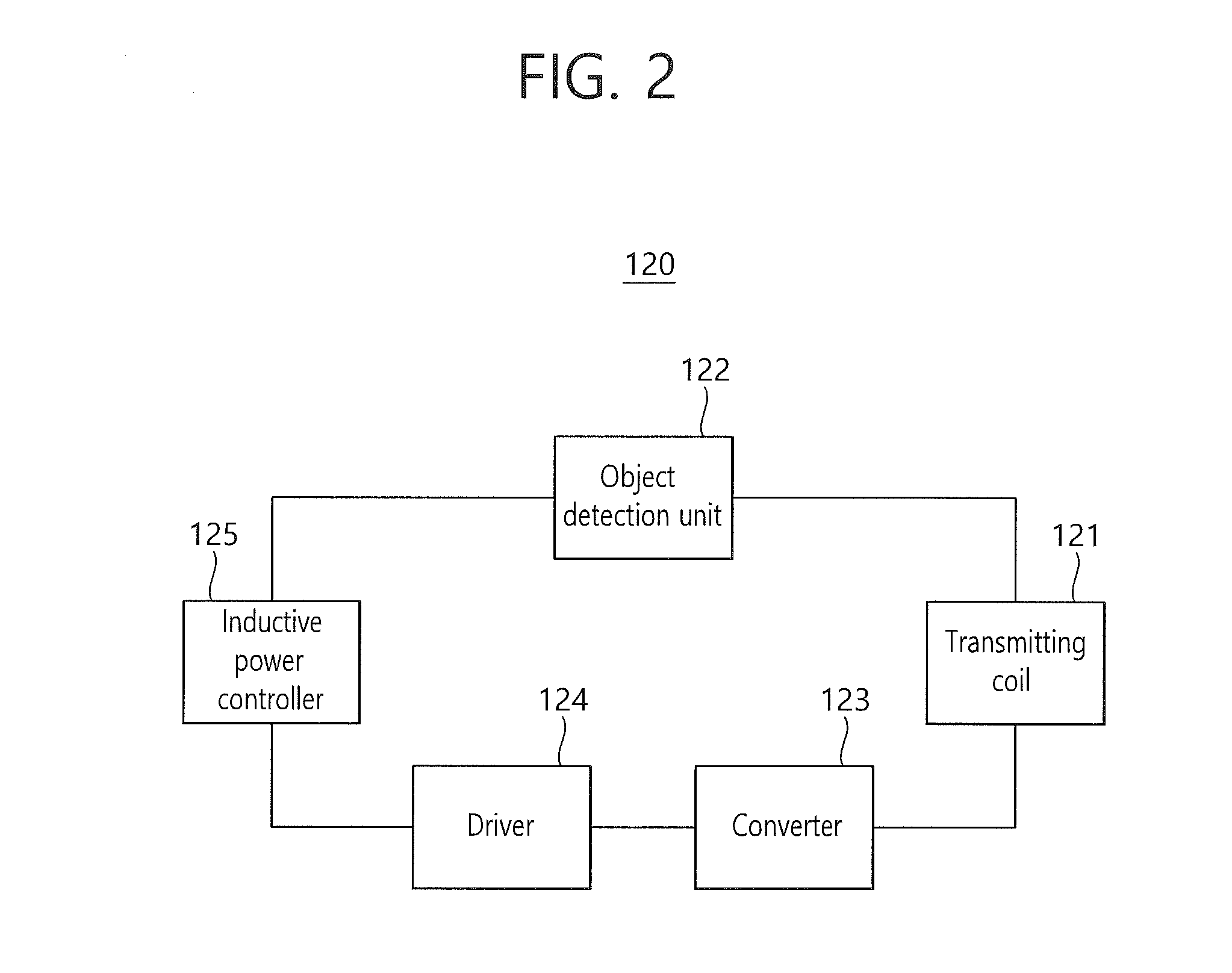
[0107]A hybrid wireless power transmitting device 1100 according to the present invention can comprise an inductive power transmitting unit 120, a magnetic resonant power transmitting unit 130, and a controller 110, where an inductive power receiving apparatus 1210, magnetic resonant receiving apparatus 1220, and hybrid receiving apparatus 1230 can be used as the wireless power receiving apparatus 1200.

[0108]To be more specific, a first object detection signal through the inductive power transmitting unit 120 and a second object detection signal through the magnetic resonant power transmitting unit 130 ar...

second embodiment

[0141]FIG. 8 is a block diagram illustrating operation of a wireless power transmitting system including a hybrid wireless power receiving apparatus according to a second embodiment of the present invention. As shown in FIG. 8, a wireless power system according to the present invention can comprise a wireless power transmitting apparatus 2100 and a wireless power receiving apparatus 2200.

[0142]A hybrid wireless power receiving apparatus 2200 according to the present invention can receive power signals (inductive power signal and resonant power signal) from both of the wireless power transmitting apparatus based on magnetic induction 220 and the wireless power transmitting apparatus based on magnetic resonance 210.

[0143]More specifically, an inductive power signal coming from the inductive power transmitting apparatus 220 is received through a receiving coil 2211 of the receiving block (refer to FIG. 9), and a resonant power signal coming from the resonant power transmitting apparatu...

third embodiment

[0174]FIG. 13 is a block diagram illustrating an electrical structure of a wireless power transmitting system capable of transmitting and receiving an inductive power signal and a resonant power signal according to a third embodiment of the present invention. As shown in FIG. 13, a wireless power system according to the present invention can comprise a wireless power transmitting apparatus 3100 and a wireless power receiving apparatus 3200.

[0175]A hybrid wireless power transmitting apparatus 3100 according to the present invention comprises a transmitting coil 3110, transmitting antenna 3120, first variable capacitor block 3130, and transmitting controller 3140, where an inductive power receiving apparatus 3201, magnetic resonant receiving apparatus 3202, and hybrid receiving apparatus 3203 can be used as the wireless power receiving apparatus 3200.

[0176]More specifically, the transmitting coil 3110 is used for transmitting an inductive power signal from a wireless power signal due ...


PUM


Abstract

The present invention provides a signal processing method performed by a hybrid wireless power transmitting apparatus which is configured to transmit wireless power signals based on magnetic resonance and magnetic induction, the method comprising transmitting a first object detection signal via an inductive power transmitting unit and a second object detection signal via a magnetic resonant power transmitting unit alternatively; operating one of the inductive power transmitting unit and the magnetic resonant power transmitting unit which is selected based on an inductive response signal and a resonant response signal corresponding to the first object detection signal and the second object detection signal respectively; and transmitting wireless power signal via the selected power transmitting unit; and a hybrid wireless power transmitting apparatus using the method.

Description

BACKGROUND OF THE INVENTION[0001]1. Field of the Invention[0002]The present invention relates to a hybrid wireless power transmitting apparatus and a method for the system.[0003]2. Related Art[0004]The advance of wireless communication technology has brought a ubiquitous information environment where people can get any information that they want at any time and any place. However, most of communication information devices still rely on batteries, and use of the devices is being limited since they receive power via power lines.[0005]Therefore, the wireless information network environment cannot be fully utilized unless the problem related to device power is solved.[0006]To solve the problem, various methods for wireless power transmission are under development, typical examples of which include a microwave receiving method, a method based on magnetic induction utilizing magnetic field, or a method based on magnetic resonance due to energy conversion between magnetic and electric fiel...

Claims


Application Information

Patent Timeline
IPC IPC(8): H02J50/12H02J7/02
CPCH02J7/025H02J50/12H02J50/10H02J50/60H02J7/00302H02J50/80H02J50/40
Inventor JUNG, CHUN-KILHWANG, BYONG-UK
Owner GE HYBRID TECH
Why Eureka
Try Eureka