Stamping Slug Retention Recess and Method

a technology of retaining recesses and slugs, which is applied in the field of die trim assembly, can solve the problems of damage to parts, expensive repair or replacement, damage to die tooling, etc., and achieve the effects of convenient addition, cost-effectiveness, and reliable securing of slugs in die trim inserts

Active Publication Date: 2016-09-08
COOPER JR DONALD
View PDF6 Cites 3 Cited by
  • Summary
  • Abstract
  • Description
  • Claims
  • Application Information

AI Technical Summary

Benefits of technology

[0018]The present disclosure relates to a new and improved die trim assembly with a groove or recess adapted to retain loose slugs during a stamping process. The recess ensures that the slug produced during a stamping operation will be retained in the die, thereby preventing loose slugs from causing the in-feeding material to jam, preventing damage to the parts being stamped, and preventing loose slugs from damaging die tooling that is expensive to repair or replace.
[0019]Unlike Kramski and Roberts, the length of the recess from the top of the die trim opening is greater than the depth of insertion of the trim punch into the die trim opening. The recess extends along the die trim opening axially parallel with the trim punch stroke. As the trim punch cuts through the material being stamped, the recess causes the slug to be cut at the top of the die trim opening with a consistent uniform tab on the slug that extends into the recess. The tab is created by normal shearing action with an established cutting clearance between the trim punch and the trim insert wall. The recess also provides a mechanical action that gradually and continuously compresses the slug material as the slug is pushed deeper into the die trim opening.
[0022]Furthermore, the increased compression of the tab at the bottom of the trim punch stroke increases lateral pressure against the slug, increasing the magnitude of the friction force generated to resist upward movement of the slug with the trim punch.
[0027]The disclosed die trim assembly has other advantages in addition to reliably securing the slug in the die trim insert. The disclosed recess can be easily added to both new and existing stamping dies, which provides a cost-effective solution to improving the stamping process.
[0028]And unlike Kramski, the disclosed recess does not require a precise relationship between the length of trim punch travel into the die trim opening and the length of the recess into the die trim opening. And unlike Roberts, the disclosed recess allows many resharpenings of the trim insert without needing to re-machine the recess.
[0029]The disclosed die trim assembly is adapted to retain slugs that is not limited by the structure of the die trim assembly. This provides flexibility with regard to the size and shape of the recess and where the recess can be added. Multiple recesses can be added, depending on the size of the loose slugs and the type of material used for stamping. The disclosed die trim assembly will greatly assist metal workers using stamping machines or die trim assemblies by retaining and securing loose slugs during a stamping process.

Problems solved by technology

This can cause the in-feeding material to jam, which can cause damage to the parts being made.
Additionally, a slug that is pulled into the working area of the stamping die can damage or break the die tooling, which is expensive to repair or replace.
A trim punch stroke that is too deep, on the other hand, would cause the trim punch to push the projection beyond the bottom of the groove.
Small fragments of the torn-off projection will accumulate in and pack into the groove, causing erosion of the projection material before the projection material engages the opening sidewall.
The fragments can be drawn upwards by the retracting trim punch to accumulate in the working area of the die, causing damage to the die tooling or the stamped parts.
In addition, Roberts U.S. Pat. No. 6,397,715 states that Kramski's groove design is expensive and difficult to machine.
Furthermore, burrs in any stamping operation are undesirable.
Broken off burrs can damage the die tooling or the stamped parts.
Pushing the burrs created by Roberts' grooves deeper along the smooth surface of the die trim opening sidewall causes slug material erosion that reduces the retention force between the slug and the die trim opening sidewall.
This increases the likelihood the slug will be unable to resist upward movement at the start of the trim punch extraction stroke.
Roberts' grooves and irregularities also increase the costs to maintain the die tooling.

Method used


Image

  • Stamping Slug Retention Recess and Method
  • Stamping Slug Retention Recess and Method
  • Stamping Slug Retention Recess and Method

Examples


first embodiment

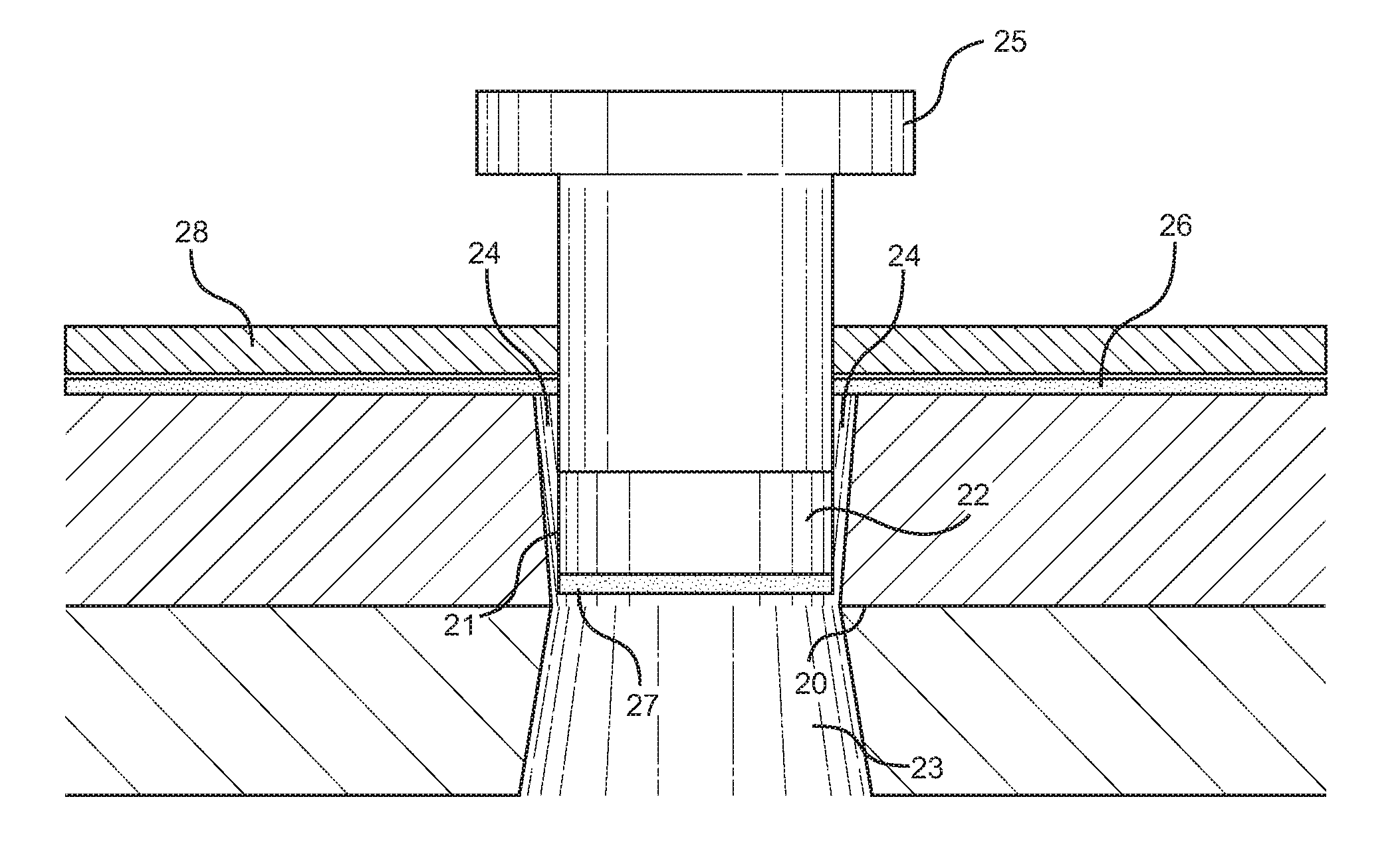
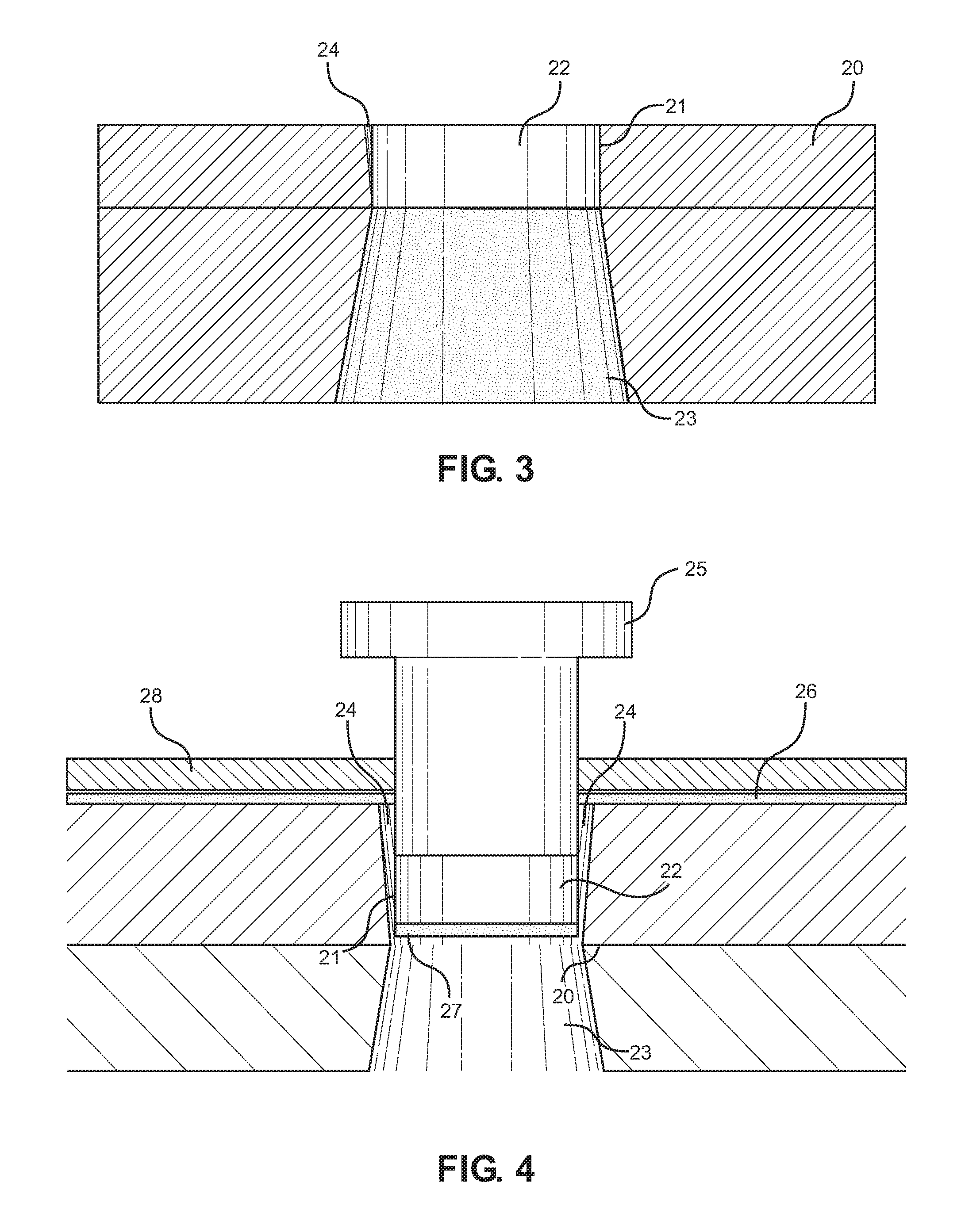
[0056]Referring now to FIG. 5, there is shown a side view of the disclosed recess, wherein the recess is created via a vertical conical extrusion. More specifically, the recess is cut with a conical shape from an angle perpendicular to the cutting edge of the die trim insert 20 such that the side of the conical extruder is aligned with a vertical axis and parallel to the die trim profile wall 21. The recess has a larger diameter at an upper portion of the recess 24, and a smaller diameter at the lower end of the recess 24. The upper portion of the recess 24 is level with the cutting edge of the die trim insert 20 and the narrower lower end of the recess 24 extends below the lower end of the die trim profile opening 22 and into the taper relief 23. Accordingly, the length of the recess 24 extends through the die trim insert 20. The die trim insert 20 is above the die trim support block 29. Die trim support block 29 has an opening that is larger than die trim profile opening 22, which...

second embodiment

[0059]Referring now to FIG. 8, there is shown a side view of the disclosed recess added via an angled conical extrusion. More specifically, the recess is cut with a side of the conical extruder that is tapered to less depth towards the bottom edge of the trim profile wall 21. In this embodiment, the recess 24 tapers to less depth as it nears the taper relief 23. Alternatively, the recess 24 may taper out at the taper relief 23. Accordingly, the length of the recess 24 is less than, equal to, or greater than the depth of the die trim profile opening 22 and is longer than the distance the trim punch enters the die trim profile opening 22. The angled conical extrusion is added to a new or existing die trim profile opening 22 using wire EDM, or other suitable methods.

[0060]Referring now to FIG. 9, there is shown a front cross-sectional view of the second embodiment of the recess 24 located on the die trim profile wall 21. The second embodiment of the recess 24 is aligned substantially v...

third embodiment

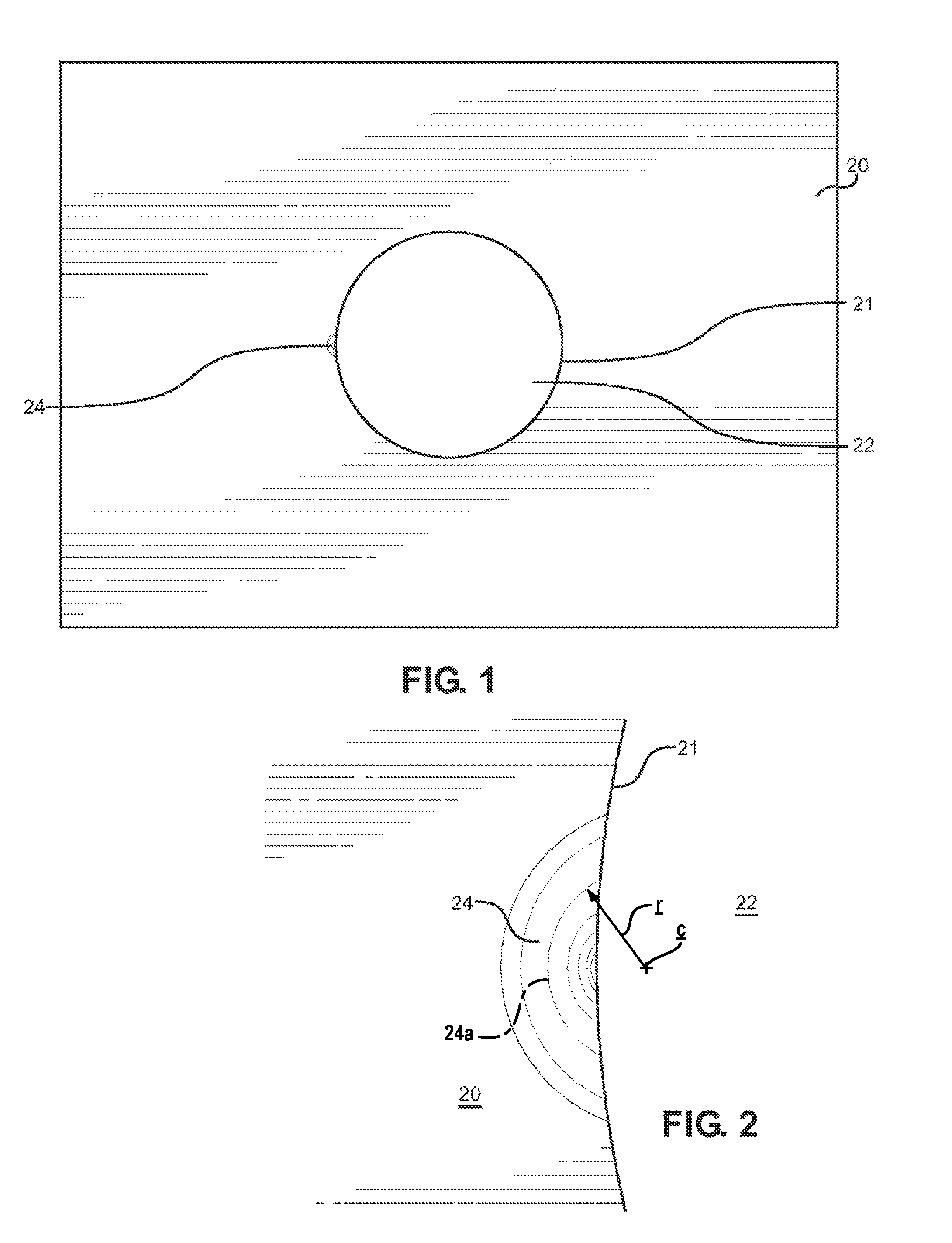
[0064]Referring now to FIGS. 12 and 13, there are shown frontal views of the disclosed recess created via an angled cylindrical extrusion. The recess 24 assumes the shape of the cylindrical cut, but the width and depth of the recess changes along its length. As such, the recess 24 captures slugs and prevents the slugs from jamming the in-feeding material. The cylindrical cut of the recess 24 has similar features as the previous embodiments. This embodiment also creates a small lug on the slug, which takes the shape of the recess at the top cutting edge. The area of the recess 24 decreases towards the bottom of the recess 24. The slug that is created near the top of the recess 24 is driven to the bottom of the recess 24, where the area of the recess 24 is now smaller. This creates a pinching action on the slug itself.

[0065]Referring now to FIGS. 14a and 14b, there are shown an embodiment of the disclosed recess in a rectangular die trim profile opening 22. Two recesses 24 are added t...


PUM

PropertyMeasurementUnit
depthaaaaaaaaaa
heightaaaaaaaaaa
cross-sectional areaaaaaaaaaaa

Abstract

Provided is a die trim section with a recess adapted to retain slugs in a stamping process. The recess may be added to existing die inserts via wire EDM, conventional surface grinding or other suitable methods. The recess extends a distance greater than the die trim punch stroke and the cross-sectional area of the recess decreases along the height of the recess.

Description

CROSS REFERENCE TO RELATED APPLICATIONS[0001]This application claims the benefit of pending U.S. patent application Ser. No. 14 / 242,925 filed on Apr. 2, 2014 at Attorney Docket No. SC318892, entitled “Stamping Slug Retention Recess”, which in turn claims the benefit of now expired U.S. Provisional Application No. 61 / 813,033 filed on Apr. 17, 2013, entitled “Saige Slug Retention Features.” The above identified patent applications are each herein incorporated by reference in its entirety to provide continuity of disclosure.FIELD OF THE DISCLOSURE[0002]The present disclosure relates to a die trim assembly with a recess adapted to retain slugs in a stamping process, and a related method for retaining slugs in a stamping process. More specifically, the present disclosure describes an improved stamping die trim assembly that retains a slug within the die trim insert after it has been blanked, and describes an improved method for retaining a slug within a die trim insert.BACKGROUND OF THE ...

Claims


Application Information

Patent Timeline
Patent Type & Authority Applications(United States)
IPC IPC(8): B21D28/14
CPCB21D28/145
Inventor COOPER, JR., DONALD
Owner COOPER JR DONALD
Why Eureka
Try Eureka