Unlock instant, AI-driven research and patent intelligence for your innovation.

Liquid fuel portable heater and control method of said heater

Inactive Publication Date: 2016-09-08
DANTHERM SPA
View PDF6 Cites 0 Cited by
  • Summary
  • Abstract
  • Description
  • Claims
  • Application Information

AI Technical Summary

Benefits of technology

The present invention provides a liquid fuel portable heater that can operate independently of the mains electricity grid and is easy to move around. It also includes an electric pump that reduces the electricity absorbed by the pump while maintaining the same nebulization pressure of the fuel.

Problems solved by technology

Since the amount of electricity required by the known heaters is very high, the known heaters require high-capacity and therefore very bulky and heavy batteries.
Furthermore, in the case of using thermoelectric cells to convert thermal energy into electricity, it would be necessary to install a very large number of cells on board, requiring extensive support surfaces around the combustion chamber to house them, entailing very large dimensions of the heater and a consequent increase in costs.
These technical limitations conflict with the need to provide a small size and lightweight portable heater with a high autonomy of operation.
A drop in capacity would in fact lead to a consequent decrease in pressure and the loss of the correct amount of fuel nebulised.
This over-sizing is materialised in excessive work by the pump, well above the actual needs of the system; said extra work is dissipated in the form of recirculation and discharge of the surplus flow upstream of the pump.
The power consumption of the pump is obviously related to how much flow it is able to deliver at a certain pressure, obviously net of output and pressure drops.
In light of the above, and in particular of the fact that the pumps fitted on known heaters are typically oversized in relation to actual needs, it follows that these heaters have a significantly higher electrical consumption than necessary, weighing heavily on the operative power reserve of battery-powered heaters or on the size thereof or on any self-generating electrical devices, such as thermoelectric cells.

Method used


Image

  • Liquid fuel portable heater and control method of said heater
  • Liquid fuel portable heater and control method of said heater
  • Liquid fuel portable heater and control method of said heater

Examples


Embodiment Construction

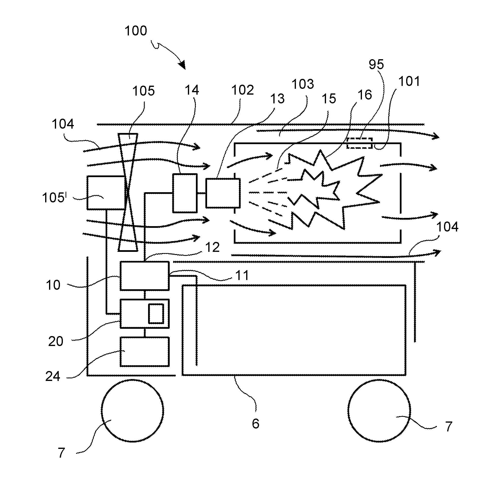
[0053]With reference to the figures, reference numeral 100 globally denotes a liquid fuel portable heater according to the invention.

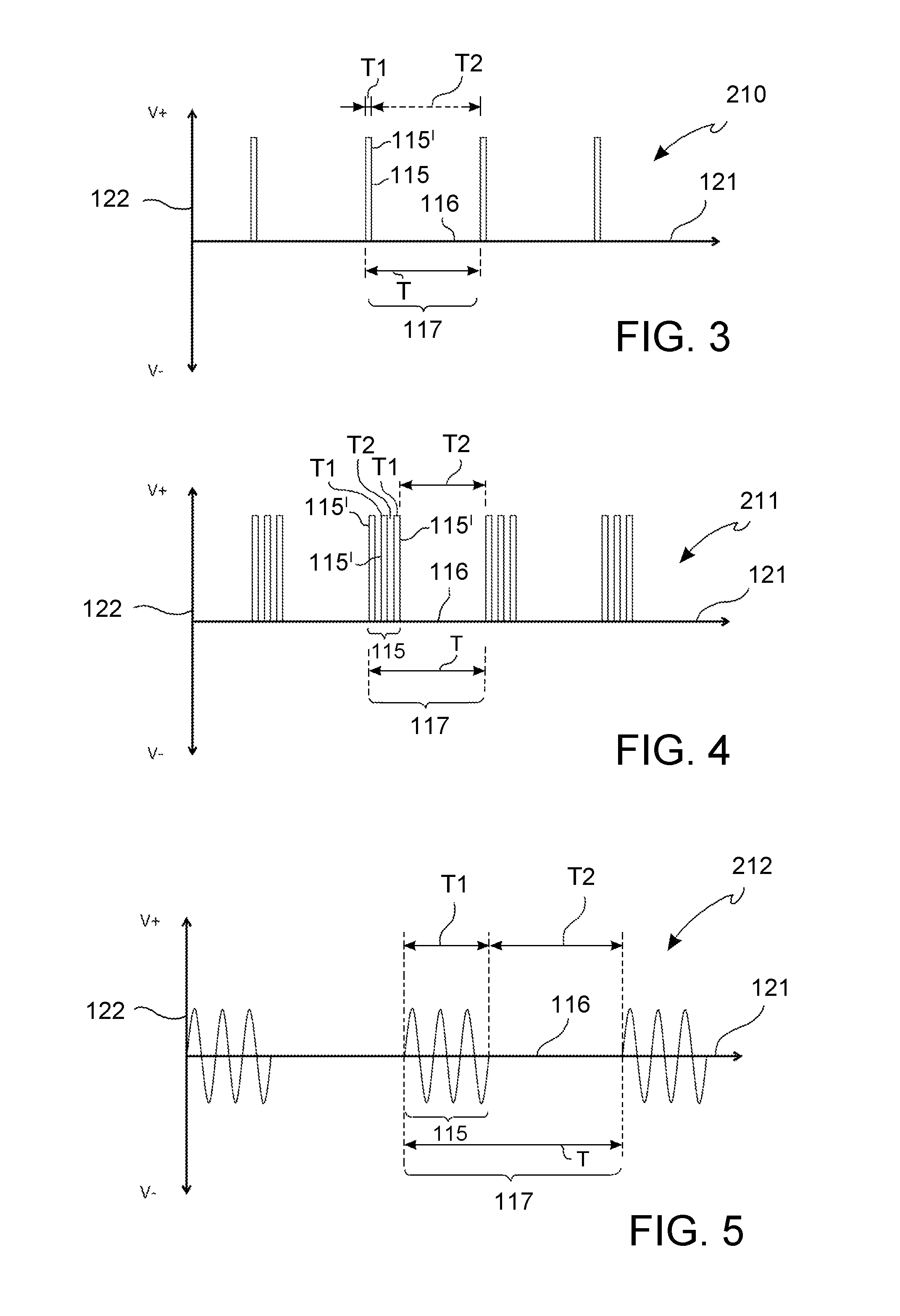
[0054]In this description, the pulse sequence of the pump power supply is also sequence of power intervals, or sequence of ON.

[0055]Consequently the duration of the pulse is the duration of the power interval and also the ON duration.

[0056]Similarly, the pause intervals are also called non-powered intervals or OFF intervals.

[0057]In addition, the interval in which the heater is switched on and thus the interval during which liquid fuel is dispensed from the nebulizer into the combustion chamber and in which combustion takes place will also be referred to as the heater operative interval,

[0058]In this description, the liquid fuel is sometimes referred to as fuel.

[0059]The heater 100 comprises a combustion chamber 101, for example of a substantially tubular shape, into which a liquid fuel, or fuel, such as diesel fuel, in the form of aerosol 15, in parti...


PUM


Abstract

A liquid fuel portable heater (100) comprises: a combustion chamber (101) having a fuel inlet with a nebuliser (13); an electric pump (10) having an inlet (11) for suctioning said liquid fuel from a tank (6), and an outlet (12) connected to said nebuliser (13); a control unit (20) configured so that, when the heater (100) is turned on, said control unit (20) supplies the electric pump with a sequence of pulses (115, 115′) with a non-zero voltage, and pause intervals (116) with a substantially zero voltage alternating with said pulses, wherein the average duration of the pulses (115, 115′) is less than the average duration of the pause intervals (116). In addition, a method for controlling an electric power supply of a fuel electric pump (10) of a liquid fuel portable heater by means of an electric control unit (20) configured to control said electric power supply, comprising a step of electrically supplying said pump, once the heater is turned on, with a sequence of pulses (115, 115′) with a non-zero voltage, and pause intervals (116) with a substantially zero voltage alternating with said pulses, wherein the average duration of the pulses (115, 115′) is less than the average duration of the pause intervals (116).

Description

SCOPE OF THE INVENTION[0001]The present invention relates to a liquid fuel portable heater optimised to reduce the consumption of electricity needed for it to operate.STATE OF THE ART[0002]Liquid fuel portable heaters generally comprise a fuel tank and a combustion chamber into which a fuel aerosol is introduced, taken from the fuel tank, which is nebulised through a nozzle nebulizer. Such known devices use an electric pump to withdraw the liquid fuel from the tank and bring it to the nebulizer nozzle at a preset pressure. Said heaters may further comprise further electrical devices needed to operate, such as a fan to convey the combustion air into the combustion chamber or to diffuse heated hot air from the combustion chamber into the environment. Solenoid valves, safety systems, electrical controls, requiring electricity to operate may also be present,[0003]Said known heaters therefore require a significant supply of electricity to operate all the internal electrical devices, amon...

Claims


Application Information

Patent Timeline
IPC IPC(8): F23D11/26F24C5/16F24C5/20F24C5/10F24C5/18
CPCF23D11/26F24C5/10F24C5/16F24C5/20F24C5/18F23K5/04F23K5/142F23N1/002F23N1/005F23N1/007F24H3/0417F23D11/24F23M2900/13003F23D2900/21003F24H3/025F23N2235/30F23N2239/06F23K2300/201
Inventor GALLETTI, DAVIDEROMAGNANI, UGOLORENZI, SERGIOGIARETTA, ENZOVERANI, STEFANO
Owner DANTHERM SPA