Laser scanning apparatus and method

a laser scanning and laser technology, applied in the field of laser scanning apparatus and method, can solve the problems of system swamped by non-desired signals and blind zones

Active Publication Date: 2016-09-08
TELEDYNE DIGITAL IMAGING INC
View PDF4 Cites 44 Cited by
  • Summary
  • Abstract
  • Description
  • Claims
  • Application Information

AI Technical Summary

Benefits of technology

[0005]In general, the disclosed embodiments relate to the challenge of dealing with multiple pulses of light that are in transit to and from the target at the same time. The goal is to prevent the outgoing and incoming pulses from being incident on the detector at the same instant, which would make the system “blind” to incoming return pulses.

Problems solved by technology

In addition to blind zones caused by the unwanted scattered light described above, under certain atmospheric conditions, blind zones can also be caused when the system detects backscattered light from the first few meters of the air below the aircraft.
Without the optical elements, the system would be swamped by non-desired signals.

Method used


Image

  • Laser scanning apparatus and method
  • Laser scanning apparatus and method
  • Laser scanning apparatus and method

Examples


Embodiment Construction

[0020]The invention summarized above may be better understood by referring to the following description, which should be read in conjunction with the accompanying drawings.

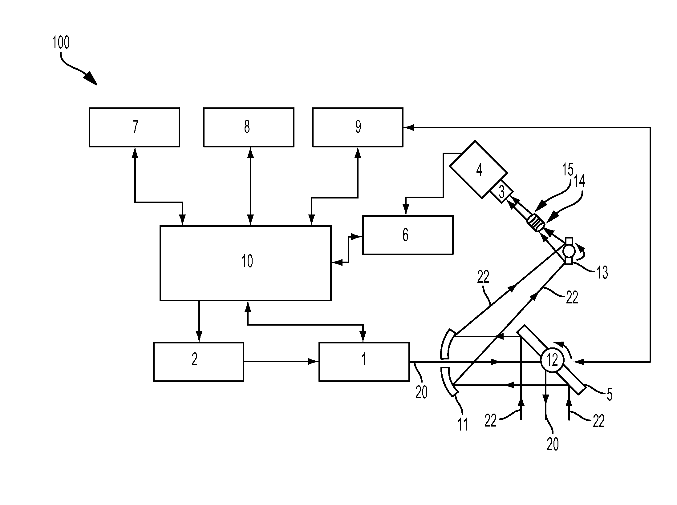
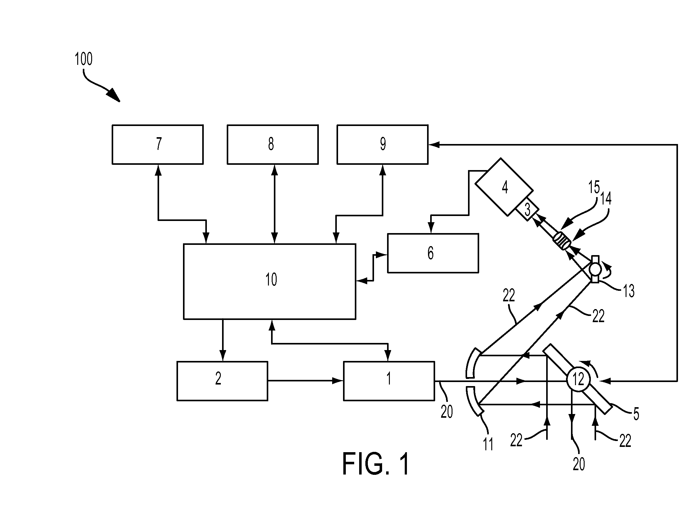
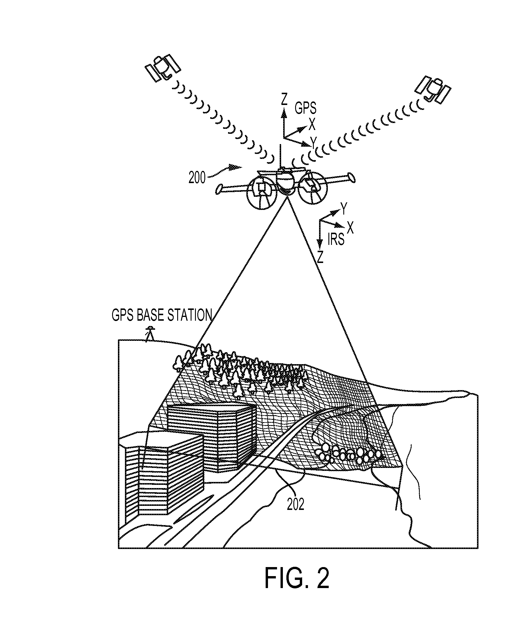
[0021]This description of an embodiment, set out below to enable one to build and use an implementation of the invention, is not intended to limit the invention, but to serve as a particular example thereof For instance, although certain embodiments described herein focuses on an airborne application of the invention, other embodiments of the invention can include ground-based laser scanning applications, using either mobile or static platforms.

[0022]Those skilled in the art should appreciate that they may readily use the conception and specific embodiments disclosed as a basis for modifying or designing other methods and systems for carrying out the same purposes of the present invention. Those skilled in the art should also realize that such equivalent assemblies do not depart from the spirit and scope of the in...


PUM


Abstract

The disclosed embodiments include an apparatus and method of using a laser to scan the ground or a target from an airborne or ground-based platform. In certain embodiments, the apparatus and method produces a 3-D elevation model of the terrain. In some embodiments, the apparatus includes a pulsed laser, a receiver to detect and amplify the pulse after being reflected by objects on the ground (or the ground itself), and electronics which measures the time of flight of the optical pulse from which the slant range to the target is calculated. Technical advantages of the disclosed embodiments include avoiding blind zones to ensure that no laser shots are wasted. In certain embodiments for airborne applications, the apparatus may also be configured to maintain a constant swath width or constant spot spacing independent of aircraft altitude or ground terrain elevation.

Description

TECHNICAL FIELD[0001]Embodiments of the invention are directed, in general, to providing an improved apparatus and method for 3-D measurement of land topography from an airborne or ground-based platform and, in particular, one that eliminates the potential loss of data that can be caused by blind zones which can occur in existing laser terrain mapping systems.BACKGROUND[0002]Airborne Laser Terrain Mapping (ALTM) systems use a Time-of-Flight (TOF) LiDAR to measure the distance from a system mounted in an aircraft, to the ground beneath the aircraft. A short pulse of visible or infra-red light is emitted by a light source such as a laser, and directed towards a target. The light pulse propagates to the target and a fraction is reflected and travels back to the LiDAR system where it is detected by a high-speed optical detector such as an avalanche photodiode, which converts the light pulse to an electrical signal which is then amplified. By measuring the time interval from the instant ...

Claims


Application Information

Patent Timeline
Patent Type & Authority Applications(United States)
IPC IPC(8): G01S17/89G01S7/48G01S17/10G01S17/86
CPCG01S7/4808G01S17/89G01B11/22G01S7/481G01S7/484G01S17/10G01S17/42G01S7/4817G01S7/4868G01S17/86
Inventor VERHEGGEN, CHRISLIADSKY, JOESITAR, MICHAELHARTSELL, DARYL
Owner TELEDYNE DIGITAL IMAGING INC
Why Eureka
Try Eureka