Support for additional decoding processing time in wireless LAN systems

a wireless lan and processing time technology, applied in the field of wireless networking, can solve the problem that it is not possible for some receiving devices, such as battery-powered receiving devices, to complete, and achieve the effect of high efficiency

Active Publication Date: 2016-09-08
ATLAS GLOBAL TECH LLC
View PDF10 Cites 14 Cited by
  • Summary
  • Abstract
  • Description
  • Claims
  • Application Information

AI Technical Summary

Benefits of technology

[0016]In an embodiment, a method of a communication device in a wireless system comprises generating a High Efficiency Physical Layer Convergence Procedure (PLCP) Protocol Data Unit (HE PPDU) frame inclu...

Problems solved by technology

As a result, it may not be possible for some receiving devices, such as battery-powered receiving devices, t...

Method used


Image

  • Support for additional decoding processing time in wireless LAN systems
  • Support for additional decoding processing time in wireless LAN systems
  • Support for additional decoding processing time in wireless LAN systems

Examples


Embodiment Construction

[0069]Embodiments of the present disclosure relate generally to wireless networking, and more particularly, to increasing an available decode time (that is, an amount of time available to decode and process) of a symbol that has been received over a wireless network.

[0070]In the following detailed description, certain illustrative embodiments have been illustrated and described. As those skilled in the art would realize, these embodiments may be modified in various different ways without departing from the scope of the present disclosure. Accordingly, the drawings and description are to be regarded as illustrative in nature and not restrictive. Like reference numerals designate like elements in the specification.

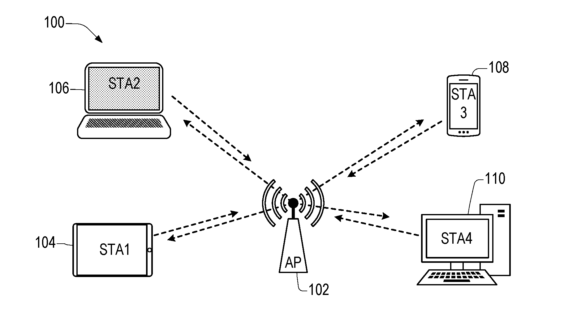
[0071]FIG. 1 illustrates a wireless network according to an embodiment. The wireless network includes an infrastructure Basic Service Set (BSS) 100 of a Wireless Local Area Network (WLAN). In an 802.11 wireless LAN, the BSS provides the basic building-block and typically inc...


PUM


Abstract

A wireless communication device in a wireless system may generate a High Efficiency Physical Layer Convergence Procedure (PLCP) Protocol Data Unit (HE PPDU) frame including (i) an Orthogonal Frequency Division Multiplexing (OFDM) symbol including padding bits and (ii) an extension having a non-zero signal strength, and transmit the HE PPDU frame. A High Efficiency signal (HE-SIG) field of the transmitted HE PPDU frame may include an indication for a duration of the extension to avoid ambiguity of the extension. A communication device in a wireless system may receive an HE PPDU frame including (i) an OFDM symbol including padding bits, and (ii) an extension having a non-zero signal strength, and transmit an Acknowledgement frame a predetermined inter-frame space after an end of the HE PPDU frame. An HE-SIG field of the received HE PPDU may include an indication for duration of the extension to avoid ambiguity of the extension.

Description

CROSS-REFERENCE TO RELATED APPLICATION[0001]This application claims the benefit of U.S. Provisional Application No. 62 / 129,717, filed on Mar. 6, 2015, the contents of which are incorporated herein by reference.BACKGROUND[0002]1. Technical Field[0003]The technology described herein relates generally to wireless networking. More particularly, the technology relates to providing additional decoding time for symbols that have been transmitted over a wireless network.[0004]2. Description of the Related Art[0005]Wireless LAN (WLAN) devices are currently being deployed in diverse environments. Some of these environments have large numbers of access points (APs) and non-AP stations in geographically limited areas. In addition, WLAN devices are increasingly required to support a variety of applications such as video, cloud access, and offloading. In particular, video traffic is expected to be the dominant type of traffic in many high efficiency WLAN deployments. With the real-time requiremen...

Claims


Application Information

Patent Timeline
IPC IPC(8): H04L29/06H04L29/08H04L5/00H04J11/00
CPCH04L69/22H04J11/00H04W84/12H04L5/0055H04L29/08018H04L69/324H04L1/1854H04L1/0041H04L1/009H04L1/1819
Inventor LEE, DAE WONMOON, SUNGHOKWON, YOUNG HOONNOH, YUJIN
Owner ATLAS GLOBAL TECH LLC
Why Eureka
Try Eureka