Thermocycler

a thermocycler and thermocycling technology, applied in biochemistry apparatus, biochemistry apparatus and processes, instruments, etc., can solve the problems of slow cycling of reaction mixtures, system drawbacks, and low temperature control, so as to improve thermal cycling speed and reduce overall cycle time

Active Publication Date: 2016-09-15
BIO MOLECULAR SYST
View PDF8 Cites 3 Cited by
  • Summary
  • Abstract
  • Description
  • Claims
  • Application Information

AI Technical Summary

Benefits of technology

[0015]The present invention relates to a high-speed thermal cycler (thermocycler) that uses a source of electromagnetic energy (EM) to heat a rotatable platform. The apparatus also provides excellent temperature control over the reaction. Preferably the electromagnetic energy is radio-frequency (RF) energy (between around 3 kHz to 300 GHz), and in one embodiment is RF energy at 50-60 kHz. In a preferred embodiment, the source of electromagnetic energy is an inductor and the rotatable platform is formed from a material which is adapted to be inductively heated when exposed to said inductor, or is in thermal communication with a material which is adapted to be inductively heated when exposed to said inductor. Preferably the rotatable platform has a plurality of reaction wells for containing the PCR reagents, or is adapted to contain a corresponding plurality of reaction / sample containers for containing, say, PCR reagents. Each reaction container is in thermal communication with the reaction well and the rotatable platform. The inductor surrounds a sufficient amount of the rotatable platform in order to heat the entire platform simultaneously, uniformly, and at high speed, irrespective of whether the platform is rotated or the speed of rotation. In one preferred embodiment, the inductor is shaped as a ring and completely surrounds the rotatable platform. This embodiment is particularly advantageous if the platform rotational speed is relatively slow or zero, as the entire platform is simultaneously heated. In another embodiment, if the speed of platform rotation is required to be relatively high, the inductor may not completely surround the platform and yet may still heat the entire platform substantially simultaneously, although the inductor surrounds a sufficient amount of the rotatable platform in order to heat the entire platform simultaneously, uniformly, and at high speed. There are various advantages which this configuration provides, as will be discussed further below.

Problems solved by technology

These devices suffer the drawback that they are slow in cycling the reaction mixtures and temperature control is less than ideal.
However, as will be appreciated, these systems suffer from their own set of drawbacks.
For example, they have a relatively limited throughput, they are physically large, prone to break down, expensive and require constant routine maintenance.
However the control and application of hot air is not efficient or readily controllable.
The disadvantage of heating the entire platform with hot air is that the surrounding structures in the device will also become heated, which will need to be cooled in the cooling phase of the cycle otherwise they will continue to radiate heat and will affect the temperature of the reactions occurring in the reaction wells.
Heating and cooling parts of the device other than the platform itself is inefficient, and temperature control using a stream of heated air is less than ideal.
Also, it is difficult to measure the temperature of the reaction mixture, which therefore needs to be estimated.
Because the temperature differential between air and the reaction mixture is very large, the estimated reaction temperature is subject to very large errors, meaning that there is poor temperature control.
This can lead to a thermal differential across the platform.
In summary, the heating methods employ non-coherent and non-focused sources of electromagnetic energy, which require high power for the reaction wells to reach the required temperature.
Additionally, heating the reactions via these conventional means can take minutes to reach the predetermined set-point temperature.

Method used


Image

  • Thermocycler
  • Thermocycler
  • Thermocycler

Examples


Embodiment Construction

[0084]The present invention will now be described with reference to the following examples which should be considered in all respects as illustrative and non-restrictive.

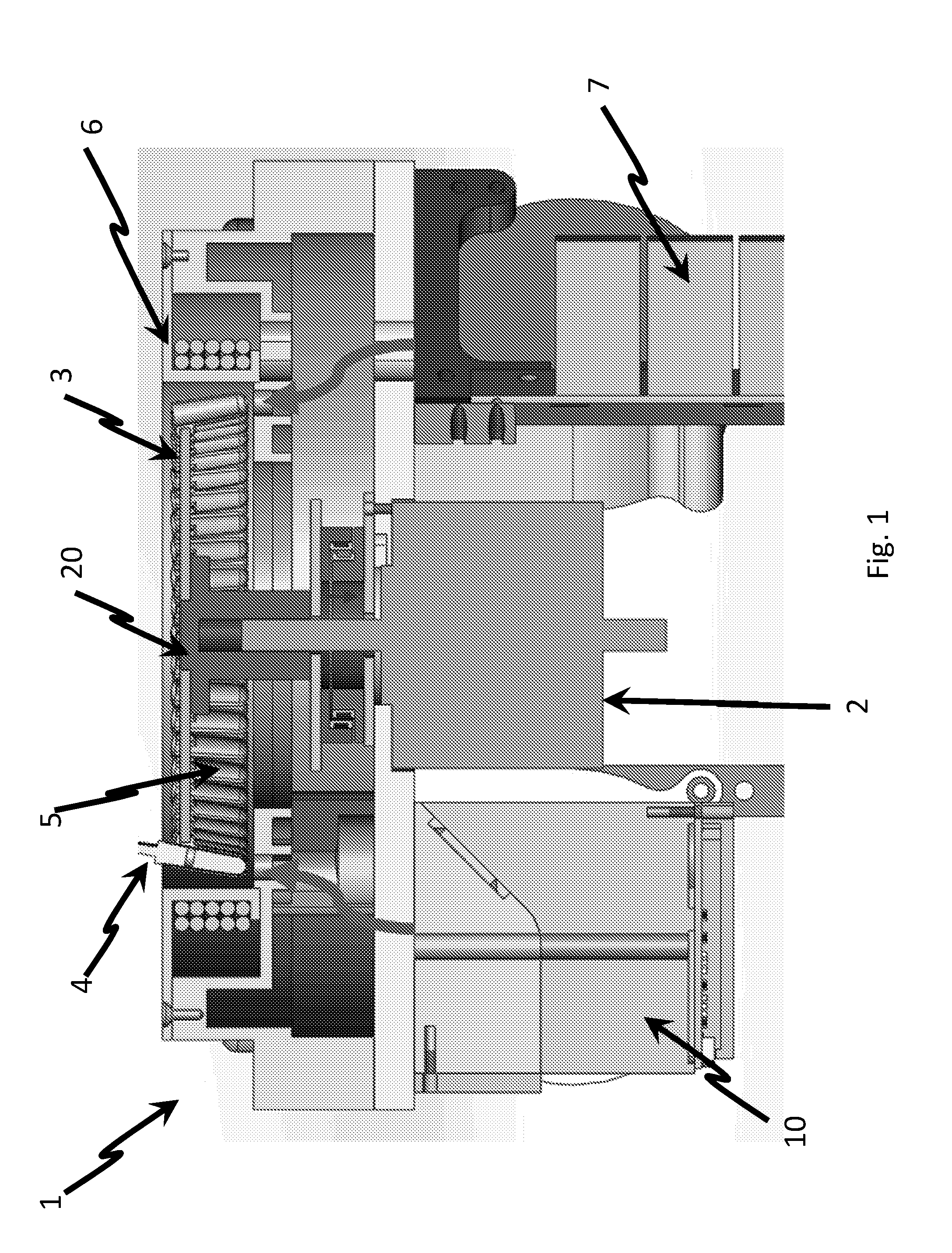
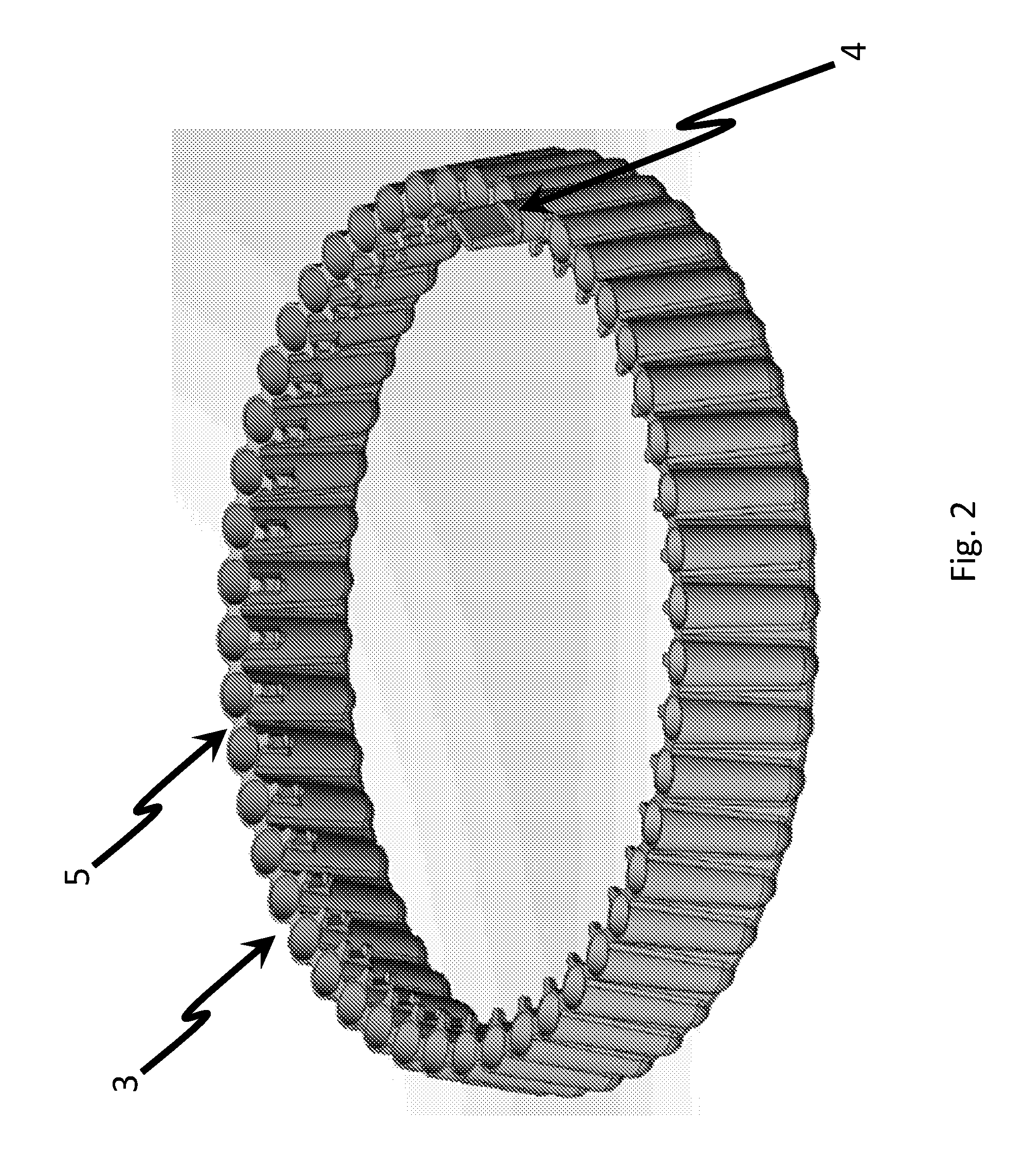
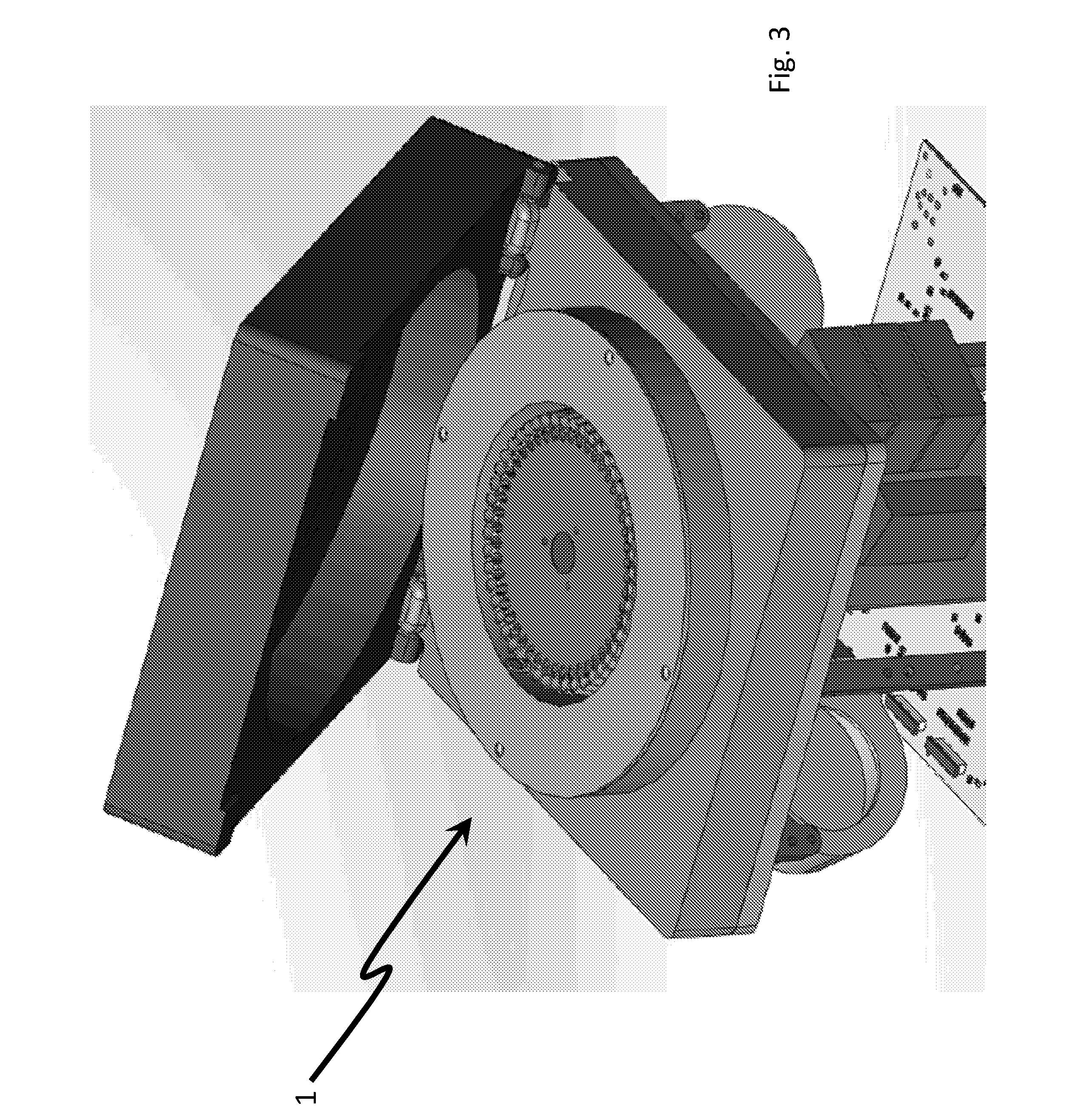
[0085]FIG. 1 shows a side sectional view of thermal cycler apparatus 1 according to the invention. The apparatus 1 comprises a drive motor 2 for rotating a rotatable platform 3 at a user-defined speed. The rotatable platform 3 is configured in a circular arrangement and is adapted to hold a plurality of plastic or glass reaction containers 4 in reaction wells 5. The rotatable platform is optionally releasably attachable to a stage 20 connected to the drive motor 2. Surrounding the rotatable platform 3 is an induction coil 6 for heating the entire rotatable platform 3 simultaneously, irrespective of whether the rotatable platform 3 is spinning or the speed of rotation. The induction coil 6 is preferably in the form of a ring.

[0086]The thermal cycler 1 of the invention is ‘high-speed’ in that it is capable of heating ...


PUM

PropertyMeasurementUnit
frequencyaaaaaaaaaa
temperatureaaaaaaaaaa

Abstract

The present invention provides a thermocycler comprising: a rotatable platform having a plurality of reaction wells or being adapted to receive a plurality of reaction containers, wherein the rotatable platform and / or the reaction wells are formed, at least in part, of a material which is adapted to be inductively heated by exposure to electromagnetic energy. An electromagnetic energy source is provided and is configured to direct electromagnetic energy at the rotatable platform, wherein the electromagnetic energy source surrounds a sufficient amount of the rotatable platform in order to heat the entire platform substantially simultaneously. In preferred embodiments, the electromagnetic energy source completely surrounds the rotatable platform. The invention further comprises a method of cycling a reaction mixture between predetermined temperatures utilising the novel thermocycler apparatus of the invention. The invention also comprises use of the novel thermocycler apparatus of the invention for conducting a nucleic acid amplification reaction such as the polymerase chain reaction (PCR) and the ligase chain reaction (LCR).

Description

FIELD OF THE INVENTION[0001]The present invention relates to an improved thermocycler, and will be described hereinafter with reference to this application. In particular, the improved thermocycler has been described herein for use in conducting nucleic acid amplification reactions. However, it will be appreciated that the invention is not limited to this particular field of use.BACKGROUND OF THE INVENTION[0002]The following discussion of the prior art is provided to place the invention in an appropriate technical context and enable the advantages of it to be more fully understood. It should be appreciated, however, that any discussion of the prior art throughout the specification should not be considered as an express or implied admission that such prior art is widely known or forms part of common general knowledge in the field.[0003]Systems which require multiple or cyclic chemical reactions to produce a desired product often require careful temperature control, and reproducible a...

Claims


Application Information

Patent Timeline
Patent Type & Authority Applications(United States)
IPC IPC(8): B01L7/00G01N35/00G01N35/04C12Q1/68G01N35/02
CPCB01L7/52C12Q1/6846G01N35/025G01N35/04G01N35/00584G01N2035/0444B01L2300/12B01L2300/0803B01L2300/0654B01L2300/1894B01L2300/1811H05B6/108B01L9/06B01L2200/147B01L2300/0806B01L2300/0841B01L3/50851C12Q1/686C12Q1/6862B01L7/00C12M1/10C12M1/34C12Q1/68G01N1/00
Inventor CORBETT, JOHNAUSTIN, JASON
Owner BIO MOLECULAR SYST
Why Eureka
Try Eureka