Vehicle suspension system

Active Publication Date: 2016-09-15
HITACHI ASTEMO LTD
View PDF19 Cites 1 Cited by
  • Summary
  • Abstract
  • Description
  • Claims
  • Application Information

AI Technical Summary

Benefits of technology

[0010]According to the present invention, it is possible to provide a vehicle suspension system enabling increased freedom in control as c

Problems solved by technology

However, manufacturing costs of the active damper are high, the mechan

Method used


Image

  • Vehicle suspension system
  • Vehicle suspension system
  • Vehicle suspension system

Examples


Example

[0021]An exemplary embodiment of the present invention will be explained with reference to the drawings.

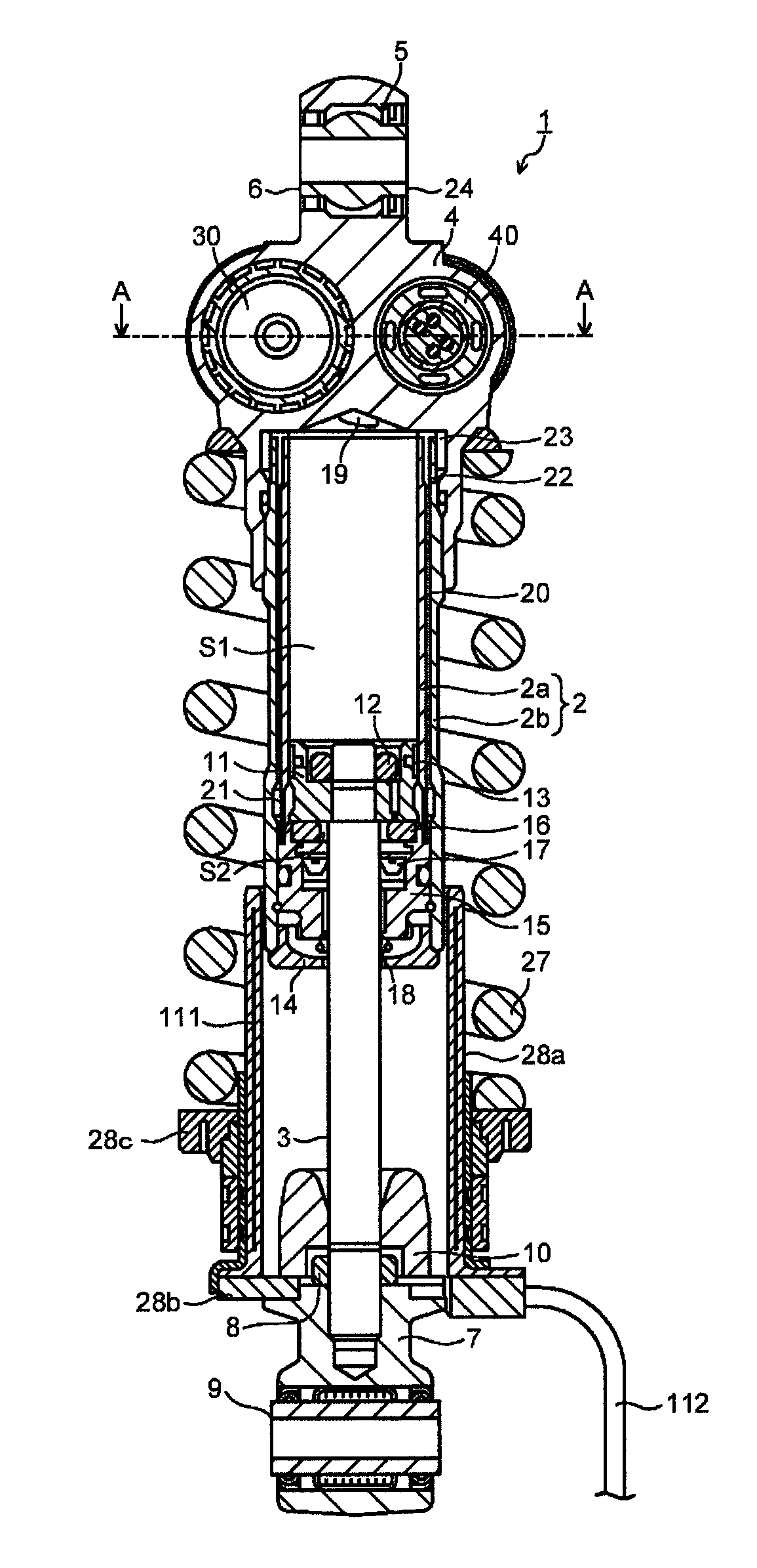
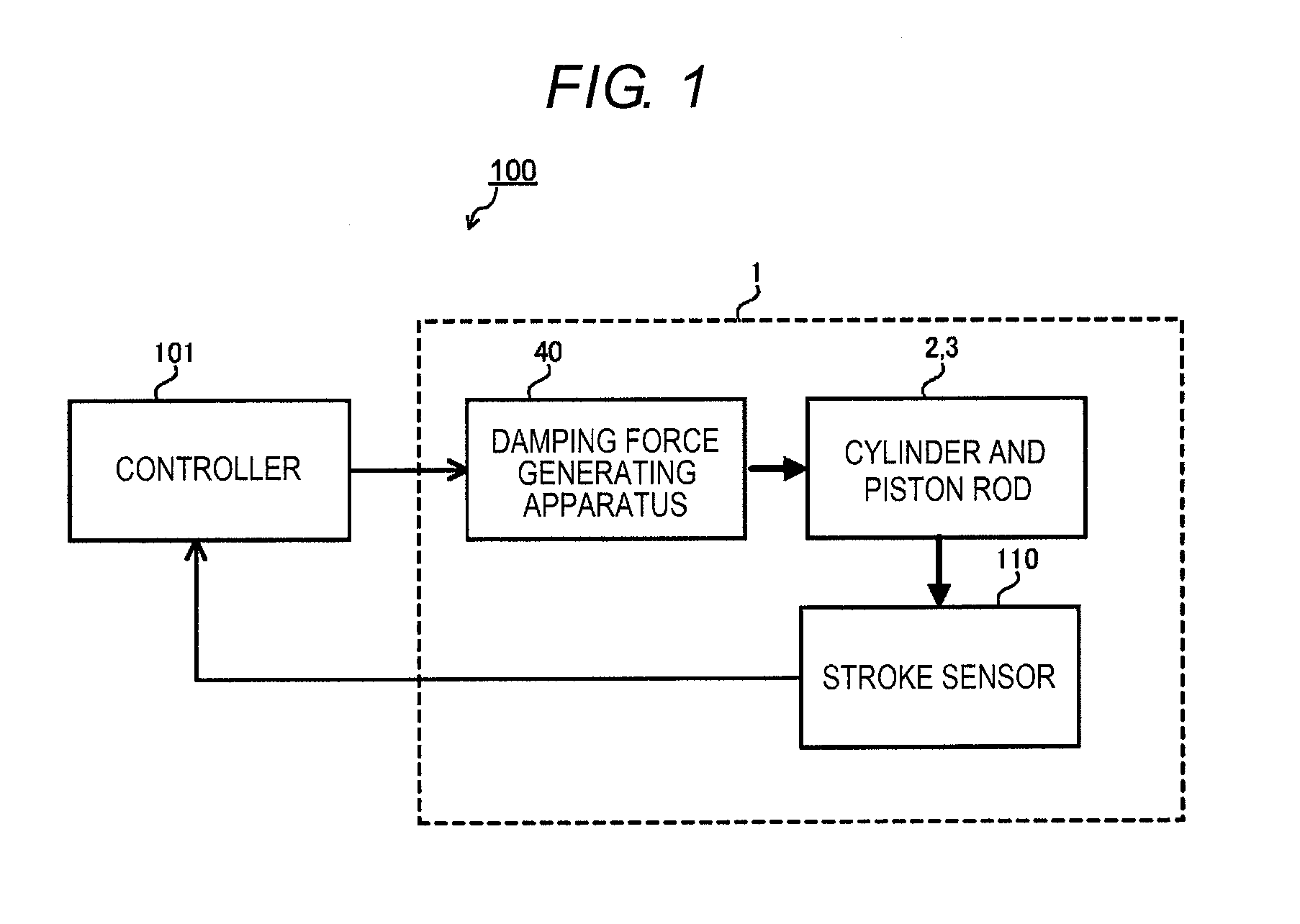
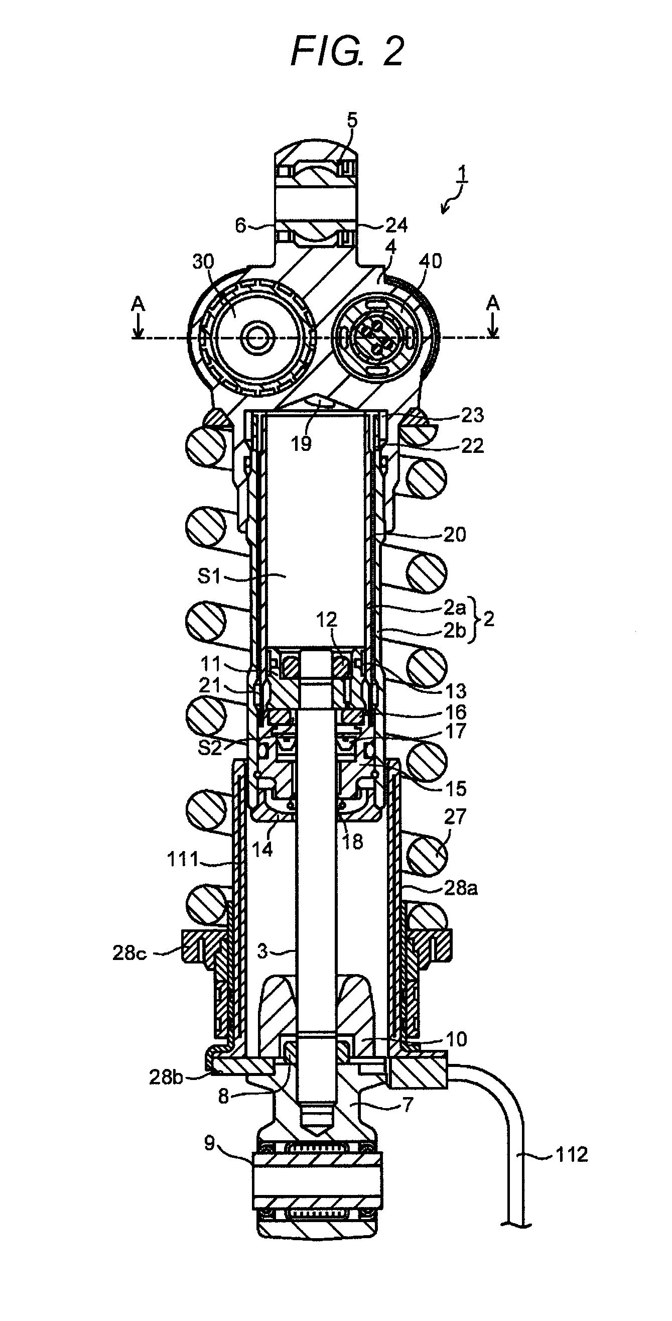
[0022]FIG. 1 is a block diagram showing a configuration of a vehicle suspension system 100 according to an embodiment. The vehicle suspension system 100 includes a shock absorber 1 and a controller 101. The shock absorber 1 includes a cylinder 2, a piston rod 3, a damping force generating apparatus 40 which generates a damping force by controlling a flow of working fluid (oil in the embodiment) filled in the cylinder 2, and a stroke sensor 110. The stroke sensor 110 detects a position of the piston rod 3 (stroke position) with respect to the cylinder 2.

[0023]The controller 101 controls the damping force generating apparatus 40 based on detection signal by the stroke sensor 110. Specifically, the controller 101 controls the damping force generating apparatus 40 so that one of an extension-side damping force and a compression-side damping force is increased and the other is reduced ...


PUM


Abstract

A vehicle suspension system includes a shock absorber having a cylinder in which a fluid is sealed, a piston slidably fitted into the cylinder, a piston rod connected to the piston and extending to an outside of the cylinder and a damping force generating apparatus controlling a flow of the fluid generated by a sliding motion of the piston inside the cylinder, a suspension spring, a detector detecting a stroke position of the piston rod with respect to the cylinder and a controller controlling the damping force generating apparatus so that one of an extension side damping force and a compression side damping force is increased and other of them is reduced in proportion to the stroke position detected by the detector.

Description

CROSS-REFERENCE TO RELATED APPLICATIONS[0001]This application is based on and claims priority under 35 USC 119 from Japanese Patent Application No. 2015-048982 filed on Mar. 12, 2015 the entire content of which is incorporated herein by reference.BACKGROUND[0002]1. Technical Field[0003]The present invention relates to a vehicle suspension system including a shock absorber having a damping force generating apparatus which generates a damping force by controlling the flow of a working fluid generated by a sliding motion of a piston inside the cylinder.[0004]2. Related Art[0005]As a shock absorber used as cushioning for a motor vehicle or a motorcycle, for example, there is known a variable attenuation damper (semi-active damper) including a cylinder in which oil is sealed as the working fluid, a piton slidably fitted into the cylinder, a piston rod connected to the piston and extending to an outside of the cylinder and a damping force generating apparatus which generates a damping for...

Claims


Application Information

Patent Timeline
IPC IPC(8): B60G17/015B60G17/08B60G15/06
CPCB60G17/0152B60G15/062B60G17/08B60G2202/31B60G2600/182B60G2400/252B60G2500/11B60G2500/10B60G2206/41B60G2300/12B62K25/10F16F9/187F16F9/48F16F9/516F16F15/002
Inventor MURAKAMI, YOSUKE
Owner HITACHI ASTEMO LTD
Why Eureka
Try Eureka