
Stacked semiconductor structure

a semiconductor structure and stacked technology, applied in semiconductor devices, semiconductor/solid-state device details, electrical apparatus, etc., can solve the problems of adverse effects on the electrical performance of the whole wafer level package, metal diffusion, etc., and achieve the effect of improving the electrical performance of the stacked semiconductor structure and superior barrier for metal diffusion

Inactive Publication Date: 2016-09-15
UNITED MICROELECTRONICS CORP
View PDF3 Cites 14 Cited by
  • Summary
  • Abstract
  • Description
  • Claims
  • Application Information

AI Technical Summary

Benefits of technology

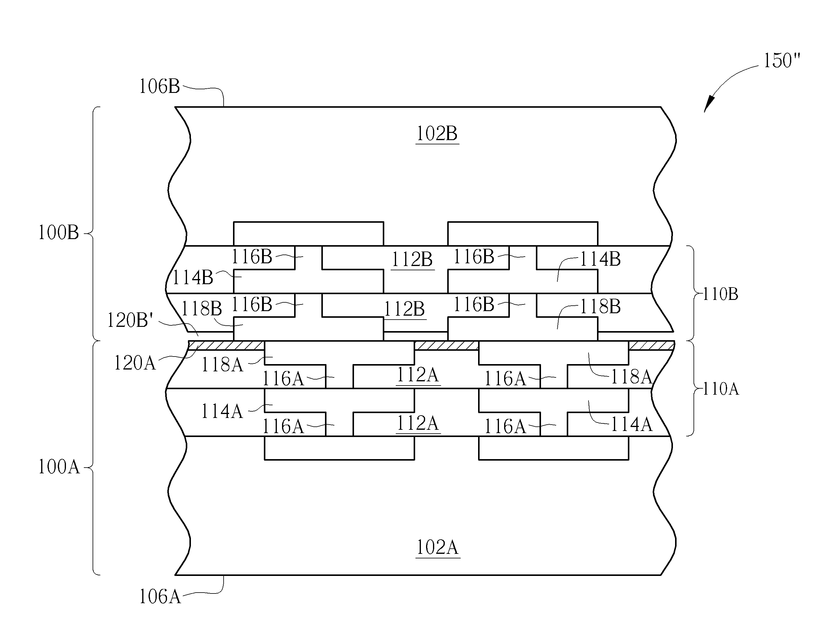
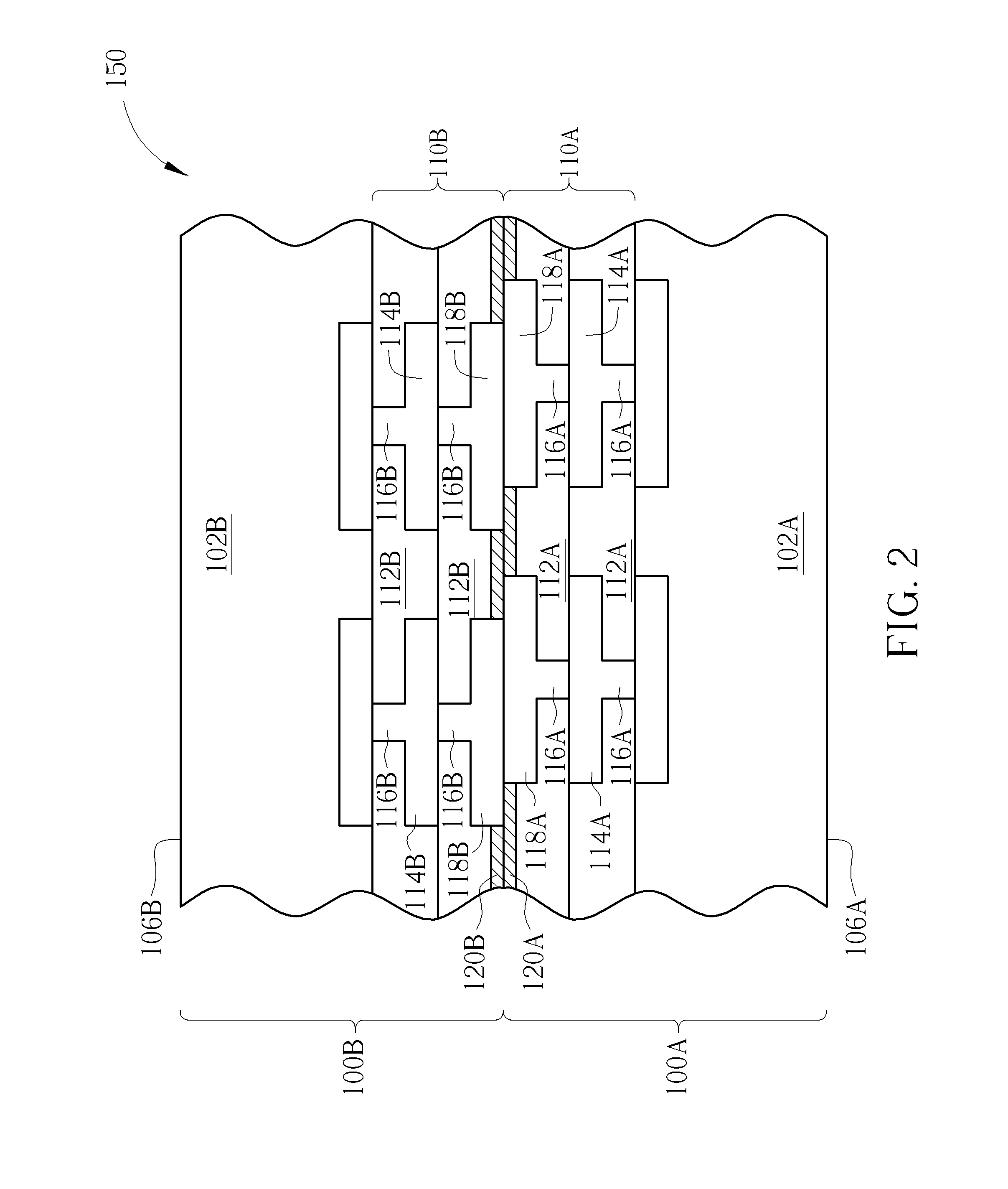
The present invention provides a stacked semiconductor structure where an insulating layer is always formed between the first and second wafers to prevent metal diffusion and improve electrical performance. This can be a solid or air insulating layer, and it serves as a superior barrier for metal diffusion. In case of misalignment, the insulating layer prevents metal diffusion between the two bonded wafers.

Problems solved by technology

It is found that when the wafers to be bonded are misaligned, the contact pads / layers exposed on one surface of the bonded wafers often contact the other wafer, and thus metal diffusion is caused.
Consequently, electrical performance of the whole wafer level package is adversely impacted due to the metal diffusion contamination.

Method used


Image

  • Stacked semiconductor structure
  • Stacked semiconductor structure
  • Stacked semiconductor structure

Examples


Embodiment Construction

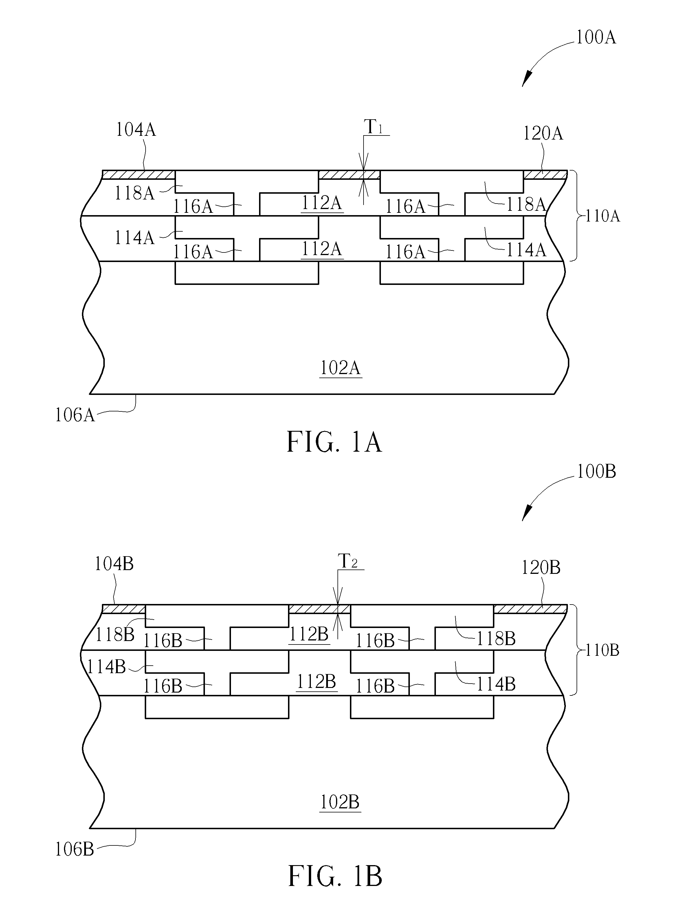
[0015]Please refer to FIGS. 1A, 1B and 2, which are drawings illustrating a stacked semiconductor structure provided by a first preferred embodiment of the present invention. As shown in FIG. 1A and FIG. 1B, the preferred embodiment provides a first wafer 100A and a second wafer 100B. The first wafer 100A and the second wafer 100B are to be bonded to form a stacked semiconductor structure such as a 3D-IC according to the preferred embodiment. The first wafer 100A can include a first substrate 102A, and at least an electronic circuitry (not shown) is formed in the first substrate 102A.

[0016]The electronic circuitry formed in the first substrate 102A includes circuitry for constructing any specific device / structure such as, for example but not limited to, memory structures, processing structures, sensors, amplifiers, power distribution, input / output circuitry, or the like. Generally, the electronic circuitry includes semiconductor devices (not shown) such as n-typed metal-oxide semico...


PUM


Abstract

A stacked semiconductor structure includes a first wafer, a second wafer, a first insulting layer, and a second insulating layer. The first wafer includes a first front surface, a first back surface, and a first interconnection structure. The first interconnection structure includes at least a first top metal layer exposed on the first front surface of the first wafer. The second wafer includes a second front surface, a second back surface, and a second interconnection structure. The second interconnection structure includes at least a second top metal layer exposed on the second front surface of the second wafer. The first insulating layer is formed on the first front surface of the first wafer, and the second insulating layer is formed on the second front surface of the second wafer. The first insulating layer and the second insulating layer contact each other.

Description

BACKGROUND OF THE INVENTION[0001]1. Field of the Invention[0002]The present invention relates to a stacked semiconductor structure, and more particularly, to a stacked semiconductor structure with wafers bonded together.[0003]2. Description of the Prior Art[0004]In an effort to increase the density and functionality of a semiconductor chip, attempts have been made to create three-dimensional integrated circuits (hereinafter abbreviated as 3D-ICs). Generally, 3D-ICs includes a plurality of semiconductor dies stacked upon each other, such as one semiconductor wafer / die bonded on top of another semiconductor wafer / die. The wafers / dies may include different functionalities or simply increase the density of a single functionality, such as a memory.[0005]Accordingly, 3D-ICs may include two wafers bonded together through suitable wafer bonding techniques. Wafer bonding involves aligning two wafers parallel to each other, bringing them in contact with each other and then applying heat and f...

Claims


Application Information

Patent Timeline
Patent Type & Authority Applications(United States)
IPC IPC(8): H01L25/065H01L23/532H01L23/48H01L23/00H01L23/522H01L23/528
CPCH01L25/0657H01L23/5226H01L23/528H01L23/481H01L24/09H01L2924/05442H01L2225/06541H01L2224/08146H01L2224/08148H01L2924/05042H01L2924/059H01L23/53295H01L24/94H01L25/50H01L2924/14H01L2924/1434H01L23/5329H01L21/76898H01L23/291H01L23/3192H01L24/05H01L24/08H01L24/80H01L2224/05571H01L2224/05647H01L2224/05684H01L2224/80097H01L2224/80895H01L2224/80896H01L2224/9202H01L2224/05572H01L2224/08121H01L2224/80194H01L2224/9212H01L2224/8034H01L2224/80357H01L2224/80359H01L2224/08145H01L2924/00014H01L2224/8203H01L2224/821H01L2224/80001H01L2224/82H01L2224/08147
Inventor LIN, SIN-SHIENWANG, FEIHSU, CHIEN-EN
Owner UNITED MICROELECTRONICS CORP
Learn More