
Multi-pole, three-phase rotary electric machine

a rotary electric machine and three-phase technology, applied in the direction of dynamo-electric machines, electrical apparatus, control systems, etc., can solve the problems of difficult fusing (thermal caulking) between the ends of the armature windings and the pitch at which the bus ring terminals are disposed would unavoidably become small, and the crowding of the connection terminals

Inactive Publication Date: 2016-09-15
HONDA MOTOR CO LTD
View PDF0 Cites 0 Cited by
  • Summary
  • Abstract
  • Description
  • Claims
  • Application Information

AI Technical Summary

Benefits of technology

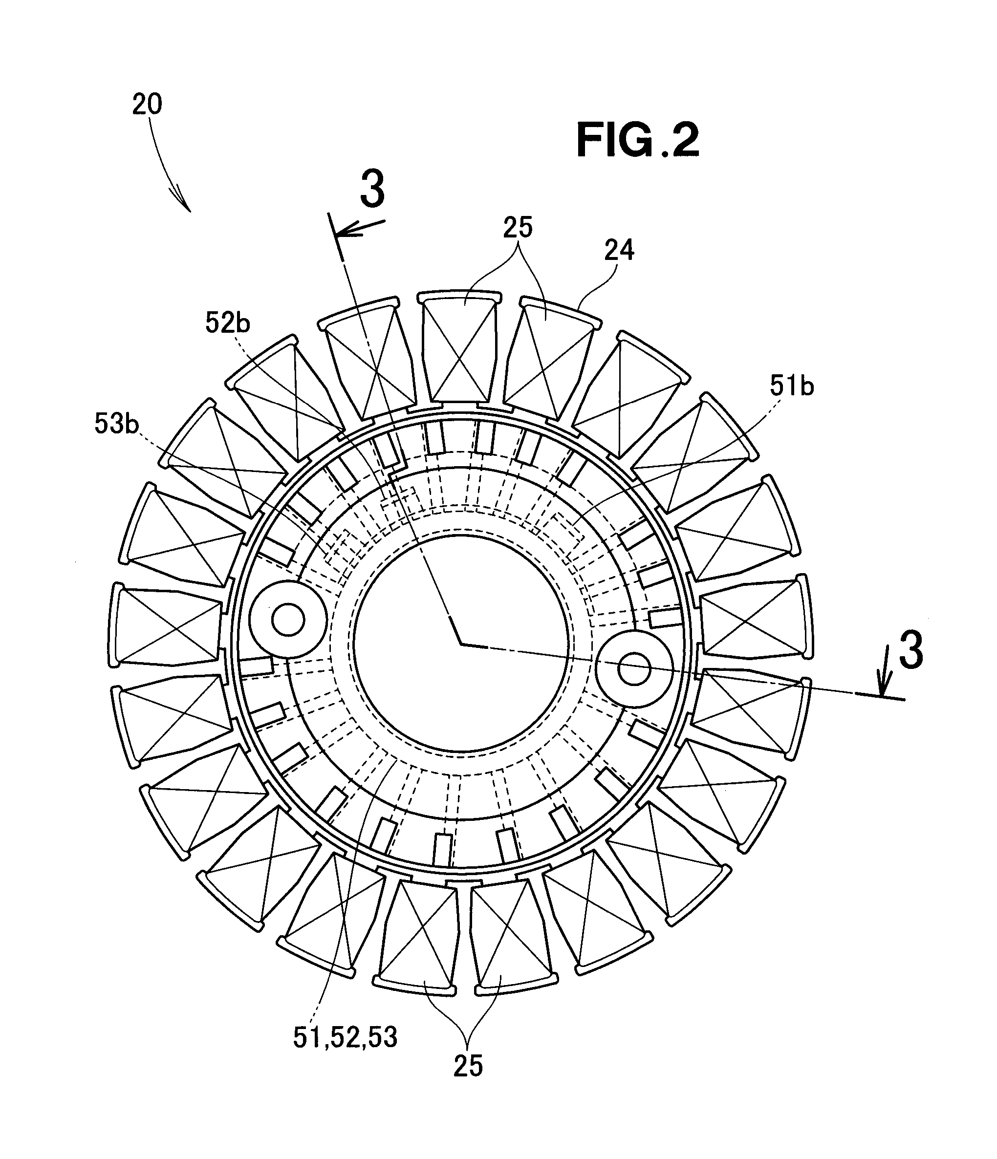
The present invention provides an improved technique for arranging multiple armature windings on a stator without close proximity between their ends. This allows for an increase in the space between terminals for connecting the windings, ensuring sufficient electrical insulation. Additionally, the invention reduces the size of the multi-pole, three-phase rotary electric machine by reducing the diameters of bus rings, while also allowing for a greater number of windings to be included without increasing the size of the bus rings. This results in a more efficient and compact stator structure.

Problems solved by technology

In the case where the parallel connection configuration is employed, the number of the connection terminals needs to be two times the number of the armature windings, which would present a problem of dense crowding of the connection terminals.
However, with the bus-ring-based structure, the multiplicity of bus ring terminals would densely crowd, and thus, a pitch at which the bus ring terminals are disposed (i.e., disposed pitch between the bus ring terminals) would unavoidably become small.
If the disposed pitch of the bus ring terminals is small like this, it is difficult to perform fusing (thermal caulking) between the ends of the armature windings and the bus ring terminals.
Thus, it is not possible to automatically manufacture a stator having a multiplicity of armature windings.
Particularly, in the case of a multi-pole electric power generating alternator that outputs a high voltage, the bus ring would excessively become large in size as compared to the stator, which would undesirably result in an increased size of the rotary electric machine.

Method used


Image

  • Multi-pole, three-phase rotary electric machine
  • Multi-pole, three-phase rotary electric machine
  • Multi-pole, three-phase rotary electric machine

Examples


Embodiment Construction

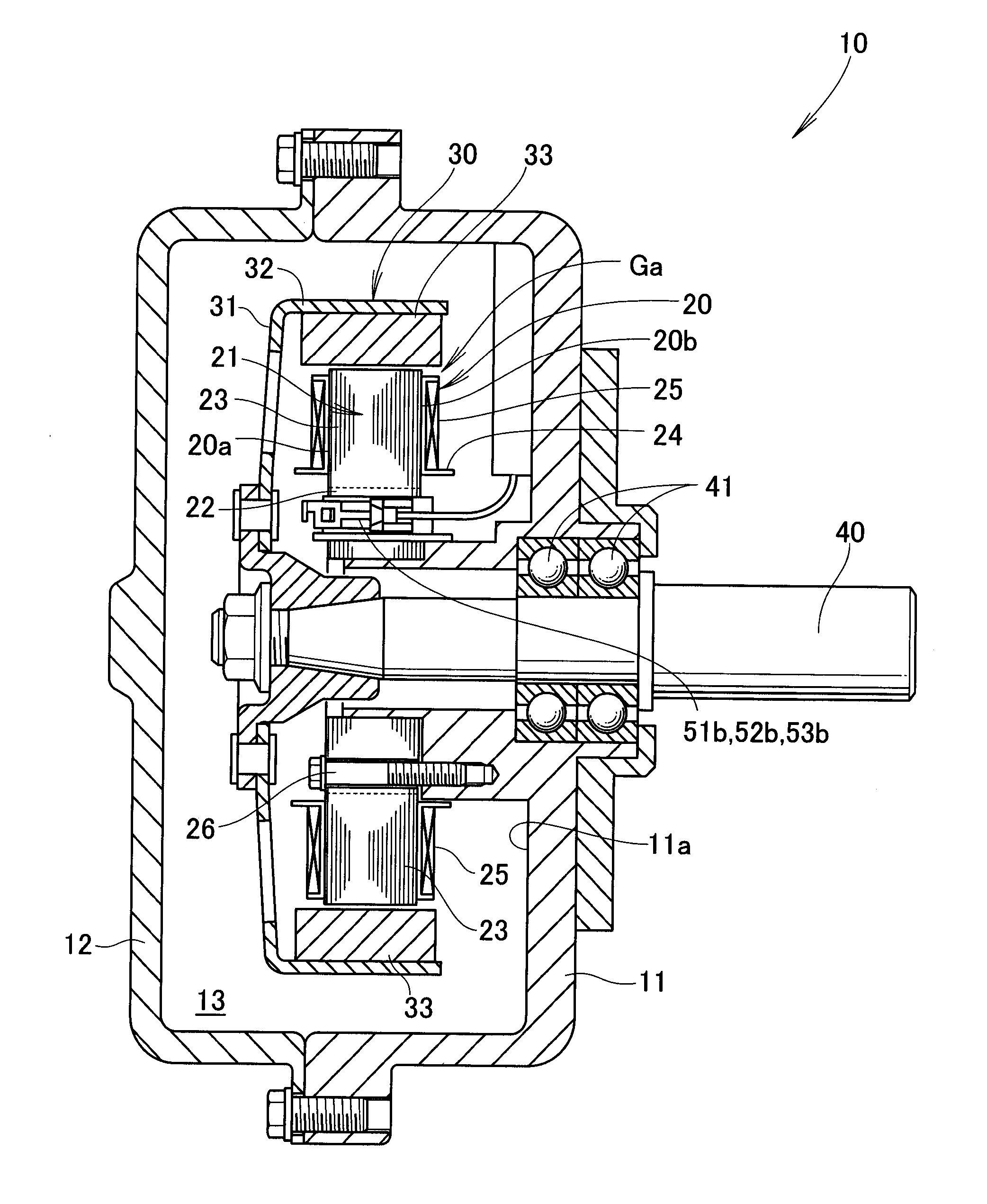
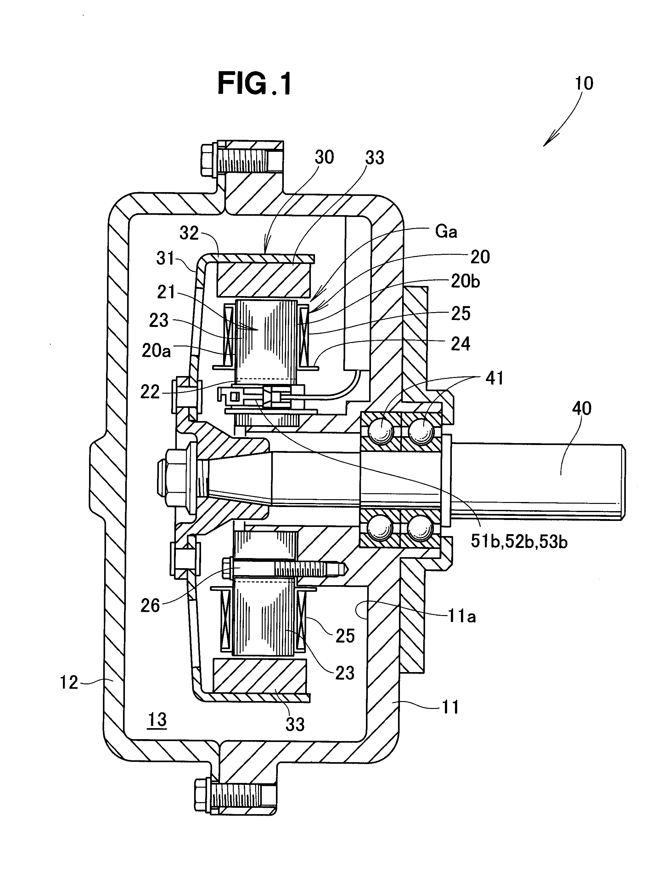
[0019]FIG. 1 is a sectional view showing an embodiment of a multi-pole, three-phase rotary electric machine 10 of the present invention. As shown, the multi-pole, three-phase rotary electric machine 10 includes a multiplicity of armature windings provided on a stator 20. Note that the multi-pole, three-phase rotary electric machine 10 is constructed as an electric motor for converting electrical energy into mechanical energy or as an electric power power generator for converting mechanical energy into electric energy. The power generator is driven, for example, by an engine. Hereinafter, the three-phase rotary electric machine 10 will be described as constructed as an electric motor.

[0020]The multi-pole, three-phase rotary electric machine 10, which is an outer-rotor type, DC brushless rotary electric machine, will hereinafter be referred to simply as “rotary electric machine 10”. The rotary electric machine 10, which has a multiplicity of poles (e.g., twenty-one poles), includes a ...


PUM


Abstract

A multi-pole, three-phase rotary electric machine includes a multiplicity of armature windings provided on a stator. Respective one ends of the armature windings are external connection ends that are connected with one another in three phases, while respective other ends of the armature windings being neutral ends that are all connected together with one another. The external connection ends of the multiplicity of armature windings are located on one axial side of the stator, and the neutral ends of the multiplicity of armature windings are located on the other axial side of the stator opposite the external connection ends.

Description

FIELD OF THE INVENTION[0001]The present invention relates to an improvement of the multi-pole, three-phase rotary electric machines where a multiplicity of armature windings are connected in parallel with one another.BACKGROUND OF THE INVENTION[0002]The conventionally-known multi-pole, three-phase rotary electric machines, each of which has a multiplicity of armature windings provided on a stator, are constructed, for example, as electric motors and electric power generators. One example of such three-phase rotary electric machines is known from Japanese Patent Application Laid-open publication No. 2009-118653.[0003]The No. 2009-118653 publication discloses an outer-rotor type three-phase, multi-pole rotary electric machine where every eight of 24 armature windings are connected in series to thereby provide three groups of windings (winding group). Thus, a three-phase winding structure is constructed of these three winding groups. Each of the winding groups is fused (thermally caulk...

Claims


Application Information

Patent Timeline
IPC IPC(8): H02K3/28
CPCH02K3/28H02K3/522H02P25/16
Inventor TAKAHASHI, MASAHIROKANEKO, NOBUYUKI
Owner HONDA MOTOR CO LTD
Learn More