
Power amplifier and input signal adjusting method

Active Publication Date: 2016-09-15
YAMAHA CORP
View PDF5 Cites 6 Cited by
  • Summary
  • Abstract
  • Description
  • Claims
  • Application Information

AI Technical Summary

Benefits of technology

The present invention aims to provide a power amplifier and an input signal adjusting method that can reproduce the same level of sound as using a different amplifier without compromising the function of the class-D amplifier. To achieve this, the amplitude of the input signal is adjusted based on the virtual output voltage of the virtual power source that occurs when a current flows through the load. This allows for adjusting the current supplied to the load by the class-D amplifier and ensures sound reproduction using various virtual power sources without affecting the function of the class-D amplifier.

Problems solved by technology

However, vacuum tube amplifiers are inconvenient to handle because they are large in size and heavy.
Vacuum tube amplifiers employ, in an output stage, a pentode that is high in output impedance and hence suffer a large loss in the output stage, which raises another problem that they cannot drive loads (speakers) efficiently.
Where such a power source having a high internal impedance is used for a class-D amplifier, a problem arises that it is difficult for the class-D amplifier to perform constant-voltage driving and hence it cannot exercise its function properly.

Method used


Image

  • Power amplifier and input signal adjusting method
  • Power amplifier and input signal adjusting method
  • Power amplifier and input signal adjusting method

Examples


Embodiment Construction

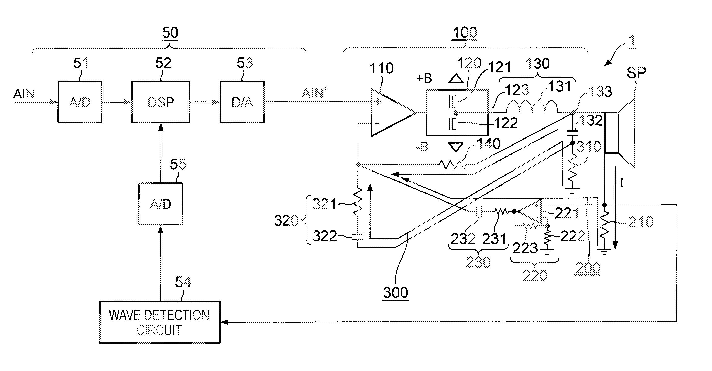
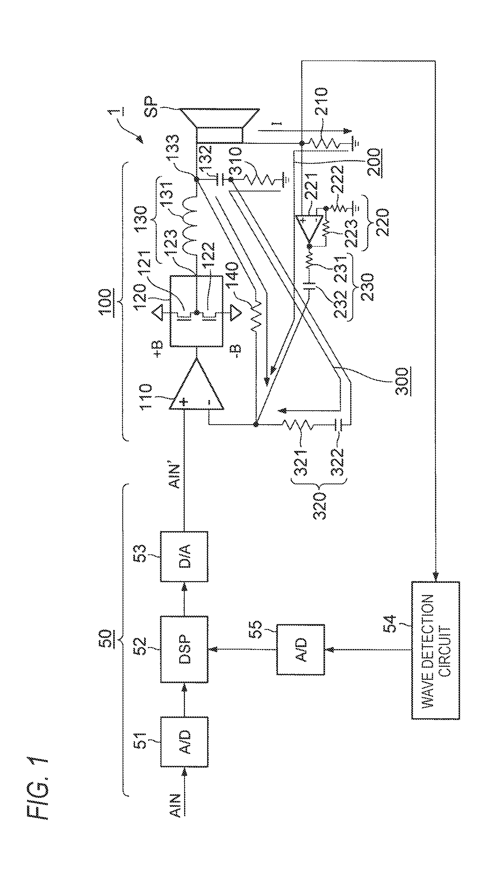
[0024]An embodiment of the present disclosure will be hereinafter described with reference to the drawings. FIG. 1 is a circuit diagram showing the configuration of a power amplifier according to the embodiment of the disclosure. To facilitate understanding of the power amplifier 1, a speaker SP which is a load of the power amplifier 1 is also illustrated in FIG. 1.

[0025]As illustrated in FIG. 1, the power amplifier 1 includes an input signal supplier 50, a class-D amplifier 100, a load current feedback circuit 200, and a filter current feedback circuit 300.

[0026]The input signal supplier 50 is a circuit for performing amplitude adjustment on an audio signal AlN that is input to the power amplifier 1 and thereby supplying an input signal AlN′ to the class-D amplifier 100. The power amplifier 1 according to the embodiment may be used as an electric guitar amplifier, in which case an output signal of the electric guitar is supplied to the input signal supplier 50 as the audio signal A...


PUM


Abstract

A power amplifier includes a class-D amplifier and an input signal supplier. The class-D amplifier includes an input portion and a switching device. The switching device is switched according to an input signal that is input to the input portion so that a current is supplied to a load from a power source via the switching device. The input signal supplier supplies the input signal to the input portion of the class-D amplifier, calculates a virtual output voltage to be output from a virtual power source having a prescribed internal impedance characteristic when a current to flow through the load is output from the virtual power source, and adjust an amplitude of the input signal according to the virtual output voltage.

Description

CROSS REFERENCE TO RELATED APPLICATIONS[0001]This application is based on Japanese Patent Application (No. P2015-050897) filed on Mar. 13, 2015 and Japanese Patent Application (No. P2015-247521) filed on Dec. 18, 2015, the contents of which are incorporated herein by reference.BACKGROUND OF THE INVENTION[0002]1. Field of the Invention[0003]The present disclosure relates to a power amplifier and, more particularly, to a power amplifier that is suitable for use as a guitar amplifier, and an input signal adjusting method.[0004]2. Description of the Related Art[0005]In recent years, power amplifiers using semiconductor devices such as class-D amplifiers have come into wide use as audio power amplifiers. For example, in class-D amplifiers, an output-stage transistor is on / off-switched by a PWM pulse sequence that is generated through pulse width modulation according to an input audio signal and a current is supplied to a speaker from a power source via the output-stage transistor. Class-...

Claims


Application Information

Patent Timeline
IPC IPC(8): H03F5/00
CPCH03F5/00H03F1/3264H03F1/327H03F3/217H04R3/00H03F2200/549
Inventor OTANI, YOHEINORO, MASAO
Owner YAMAHA CORP
Learn More