Transmission-reception device

a technology of a reception device and a receiver, which is applied in the direction of digital transmission, electrical equipment, modulated carrier system, etc., can solve the problem of deterioration of the s/n of the reception signal on the second communication band

Active Publication Date: 2016-09-15
MURATA MFG CO LTD
View PDF16 Cites 4 Cited by
  • Summary
  • Abstract
  • Description
  • Claims
  • Application Information

AI Technical Summary

Benefits of technology

[0015]With this configuration, the harmonic signal reflected by the antenna and the harmonic signal leaking from the first RF circuit side to the second RF circuit side through the antenna duplexer can be more precisely canceled with the harmonic signal which is demultiplexed by the demultiplexer and the amplitude and the phase of which are adjusted by the signal adjusting unit, more precisely.

Problems solved by technology

However, when transmission on a first communication band and reception on a second communication band are simultaneously executed by using a common antenna, a transmission signal on the first communication band may enter a reception circuit for the second communication band and may deteriorate S / N of a reception signal on the second communication band.

Method used


Image

  • Transmission-reception device
  • Transmission-reception device
  • Transmission-reception device

Examples


Embodiment Construction

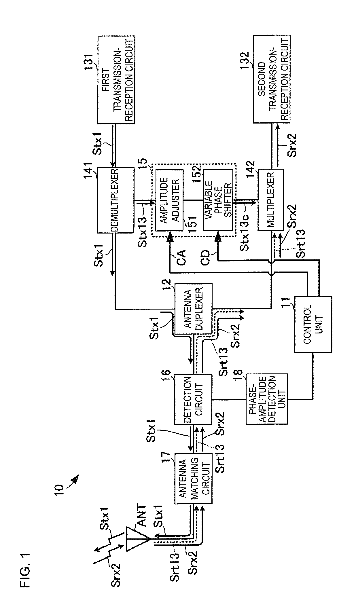
[0031]A transmission-reception device according to a first embodiment of the present disclosure is described with reference to the drawings. FIG. 1 is a circuit block diagram of the transmission-reception device according to the first embodiment of the present disclosure.

[0032]A transmission-reception device 10 includes a control unit 11, an antenna duplexer 12, first and second transmission-reception circuits 131 and 132, a demultiplexer 141, a multiplexer 142, a signal adjusting unit 15, a detection circuit 16, an antenna matching circuit 17, a phase-amplitude detection unit 18, and an antenna ANT. The first transmission-reception circuit 131 corresponds to a first RF circuit of the present disclosure, the second transmission-reception circuit 132 corresponds to a second RF circuit of the present disclosure, and a circuit including the detection circuit 16 and the phase-amplitude detection unit 18 correspond to a sensing unit of the present disclosure.

[0033]The first transmission-...


PUM


Abstract

A transmission-reception device includes an antenna duplexer, an antenna, and first and second transmission-reception circuits. A demultiplexer is connected between the first transmission-reception circuit and the antenna duplexer, and a multiplexer is connected between the second transmission-reception circuit and the antenna duplexer. A signal adjusting unit is connected between the demultiplexer and the multiplexer. The amplitude and phase of a third harmonic signal of a first transmission signal reflected by the antenna are detected. The signal adjusting unit adjusts the amplitude and phase of the third harmonic signal demultiplexed by the demultiplexer on the basis of the detection results, and outputs a cancel signal. The multiplexer synthesizes and hence cancels the third harmonic signal reflected by the antenna and the cancel signal with each other.

Description

BACKGROUNDTechnical Field[0001]The present disclosure relates to a transmission-reception device compliant with carrier aggregation that simultaneously executes transmission and reception on a plurality of communication bands.[0002]There is currently requested an increase in communication speed, and various communication devices compliant with carrier aggregation are suggested. For example, Patent Document 1 describes a communication device including a plurality of antennas. The antennas simultaneously execute transmission and reception on different communication bands.[0003]However, the plurality of antennas may not be occasionally provided due to, for example, a decrease in size of the communication device.[0004]In such a case, transmission and reception on the plurality of communication bands have to be simultaneously executed by using a single antenna. Transmission and reception on the plurality of communication bands are simultaneously executed with a single antenna by using a ...

Claims


Application Information

Patent Timeline
Patent Type & Authority Applications(United States)
IPC IPC(8): H04B1/525H04L5/14
CPCH04L5/14H04B1/525H04L5/001H04L2027/0051
Inventor OBIYA, HIDENORIMIZOGUCHI, SHINYAHITOMI, SHINYA
Owner MURATA MFG CO LTD
Why Eureka
Try Eureka