Intraocular Lens Injector, Method For Folding An Intraocular Lens And Intraocular Lens Injector System

a technology of intraocular lens and injector system, which is applied in the field of intraocular lens injector, can solve the problems of reducing visual quality, difficult to fold, and difficult injection of three-piece iols, so as to avoid deformation of trailing haptic, and avoid high stress during folding

Active Publication Date: 2016-09-22
ATTINGER TECHN
View PDF23 Cites 24 Cited by
  • Summary
  • Abstract
  • Description
  • Claims
  • Application Information

AI Technical Summary

Benefits of technology

[0015]One advantage of the invention is that the trailing haptic of an IOL is folded in a clearly defined, reproducible method step, thus avoiding high stress during folding and thus avoiding deforming the trailing haptic. In a preferred method and embodiment, the leading haptic is also folded in a clearly defined, reproducible method step, thus also avoiding high stress during folding. The folding is achieved without any direct manipulation of the IOL by a surgeon, as this was known in the state of the art, where the IOL had to be folded using a forceps. In addition the IOL has to be inserted into the IOL injector in a clearly defined orientation, thus leaving no space for erroneous placing the IOL in the injector. After folding, the IOL is pushed through a cavity and an injection nozzle in a clearly defined orientation, without any direct intervention, so that the whole IOL, after the haptics having been folded, is compacted in a clearly defined, reproducible step, thus avoiding high stress during compacting within the cartridge.
[0016]In a preferred embodiment, the IOL injector comprises only one pushing plunger that has to be pushed, for example at the thumb plate, even though the IOL injector comprises two plungers, a pushing plunger and a folding plunger that move within the injector body. Because in a preferred embodiment the folding plunger to a certain extent is connected with the pushing plunger, it is sufficient for a surgeon to activate only the pushing plunger for folding the IOL and pushing the IOL through the cartridge 5 and the injection nozzle 5a. One advantage of the IOL injector according to the invention therefore is that a surgeon is very familiar with handling such an injector, having only one single plunger to push. In addition the IOL injector according to the invention can consist of an injector body (a hand piece) and a separate cartridge, whereby the injector body is reusable or disposable and the separate cartridge is disposable. The IOL injector according to the invention can also be configured as a preloaded injector. The handling of both systems is very similar, so that a surgeon may use both systems, a preloaded system or a loadable system, without additional training. This also increases flexibility and safety, and decreases the cost for stocking and handling the injector system.
[0017]Various objects, features, aspects and advantages of the present invention will become more apparent from the following detailed description of preferred embodiments of the invention, along with the accompanying drawings in which like numerals represent like components.

Problems solved by technology

Depending on the type of correction, even little decentration and tilt of an IOL in the eye may decrease visual quality.
The three piece IOLs are more difficult to inject as the haptics are difficult to fold and more fragile and susceptible to plunger damage.
One disadvantage of such common technique therefore is that haptics will most likely be deformed during the implantation procedure, due to mechanical stress on the haptics during folding with the forceps and / or during insertion with the injector.
As a consequence the position of the IOL in the optical system of the eye may not be correct.
An additional disadvantage is that the folding of the IOL requires a separate step when preparing the injector for injecting the IOL.
An additional disadvantage is that the insertion of a multipiece IOL is less predictable than a single-piece IOL in terms of tilt and decentration.
In addition common injectors are not reliable and easy to handle.
One disadvantage of such completely different injector systems is that the handling is completely different.
This is a potential risk for a surgeon, because the preparation of the injector and the handling of the injector during insertion into the eye are different, so that additional training is required.
It is therefore difficult to change from one type of injector system to the other, which restricts flexibility, and increases the cost for stocking and handling the injector system.
Disadvantages of this injector are that inserting the IOL into the injector is difficult and demanding, that the IOL, in particular the haptics might be damaged during insertion of the IOL into the injector, and that the haptics might be damaged when the plunger folds the haptic and squeezes the IOL through the injection tube.
A high pressure is acting onto the haptics when the plunger folds the haptic and squeezes the IOL through the injection tube, therefore the haptics might be damaged.
Disadvantages of this IOL injector are that it is difficult to handle when inserting the IOL into the eye, and that handling errors may occur during insertion.
In addition the IOL injector is only suitable for preloaded systems.

Method used


Image

  • Intraocular Lens Injector, Method For Folding An Intraocular Lens And Intraocular Lens Injector System
  • Intraocular Lens Injector, Method For Folding An Intraocular Lens And Intraocular Lens Injector System
  • Intraocular Lens Injector, Method For Folding An Intraocular Lens And Intraocular Lens Injector System

Examples


Embodiment Construction

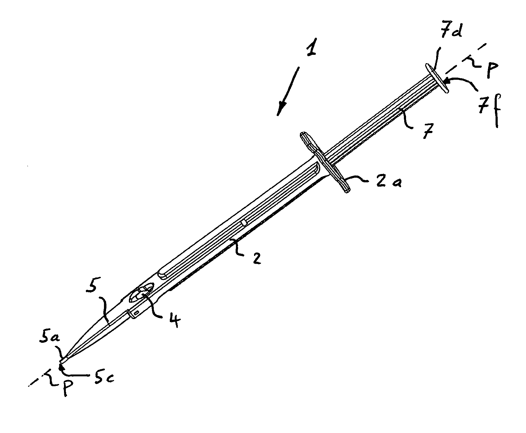
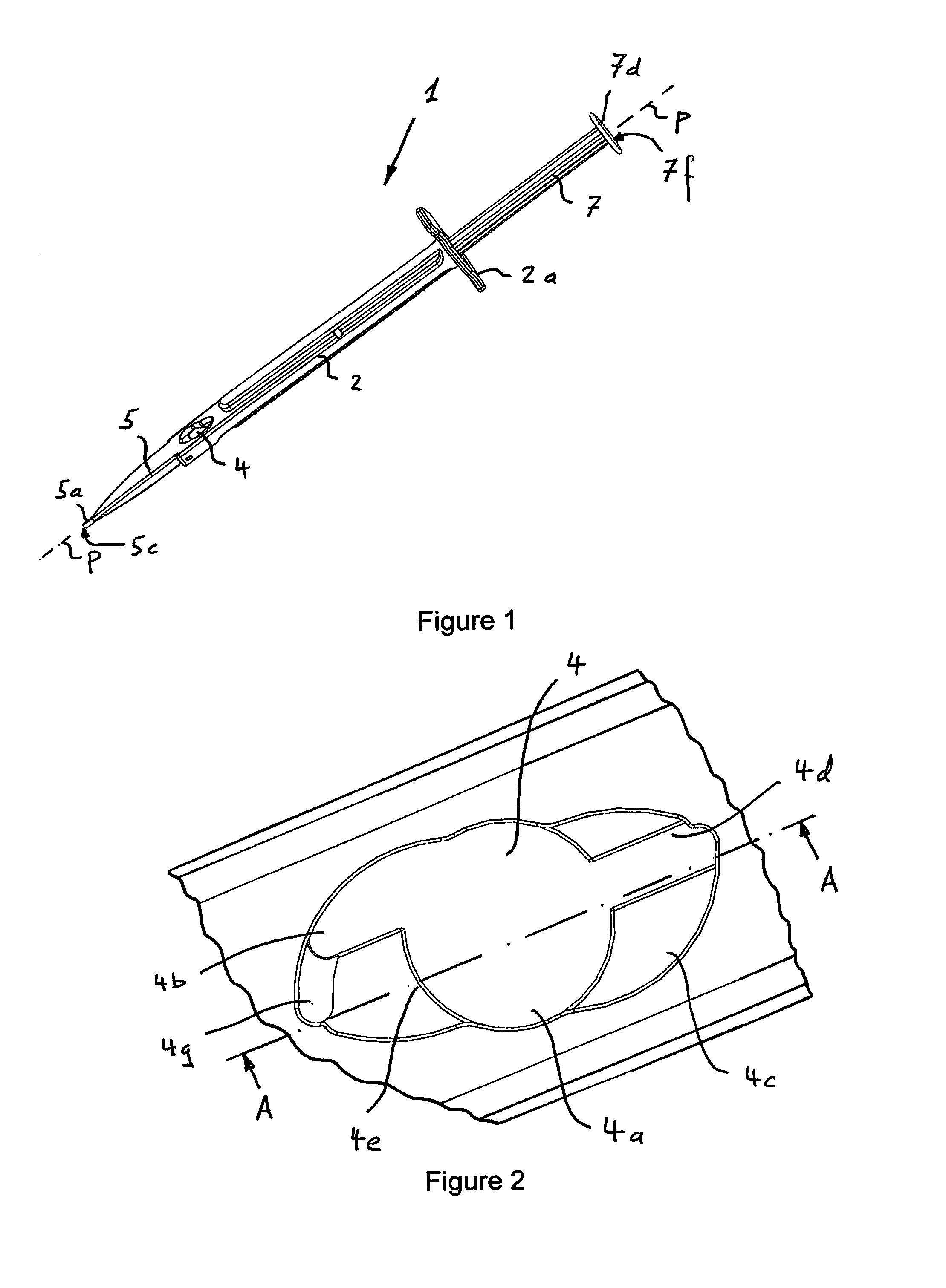
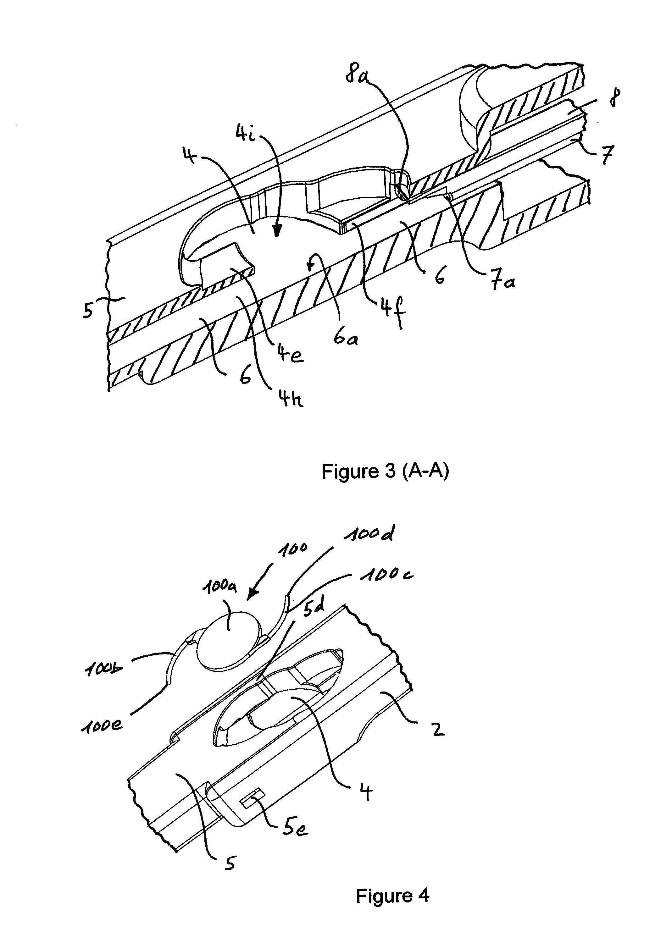
[0040]A preferred embodiment of the IOL injector 1 according to the present invention is shown in different views and cross sections in FIGS. 1 to 16. The IOL injector 1 shown in FIG. 1 includes an injector body 2 having a channel 6 extending in direction of the longitudinal axis P, along with a pushing plunger 7 slidably inserted in the injector body 2. The injector 1 further includes a cavity 4 for inserting an intraocular lens 100, and further includes a cartridge 5 with an injection nozzle 5a that ends at a distal end 5c. The injector body 2 having two finger grips 2a. The pushing plunger 7 at the opposite end of the distal end 5c having a thumb plate 7d, which also forms the proximal end 7f of the plunger 7, respectively the IOL injector 1. The channel 6 is extending through the injector body 2, the cavity 4 as well as the cartridge 5 and exits at the distal end 5c of the injection nozzle 5a, so that the pushing plunger 7 may advance an intraocular lens 100 positioned in the ca...


PUM


Abstract

IOL (intraocular lens) injector (1) for introducing an IOL (100) into the eye, comprising: an injector body (2); a cavity (4) for holding the IOL (100) comprising a leading haptic (100b) and a trailing haptic (100c); a cartridge (5) ending at a distal end (5c) in an injection nozzle (5a); the injector body (2), the cavity (4) and the cartridge (5) having a channel (6) extending in axial direction (P); and an axially movable pushing plunger (7) being placed in the channel (6) of the injector body (2) for pushing the IOL (100) in axial direction (P) out of the cavity (4) and into the cartridge (5) and the injection nozzle (5a), wherein a folding plunger (8) is arranged in the channel (6) and is extending in axial direction (P), parallel to the pushing plunger (7); and wherein the cavity (4) comprises a trailing haptic rest (4c) for defining the direction of the trailing haptic (100c) of an IOL (100) arrange in the cavity (4), such that the folding plunger (8) when moved in axial direction (P) hits the trailing haptic (100c) of the IOL (100).

Description

FIELD OF THE INVENTION[0001]The field of invention relates to an intraocular lens injector. The field of invention further relates to a method for folding an intraocular lens in an intraocular lens injector. The field of invention further relates to an intraocular lens injector system comprising an intraocular lens injector and an intraocular lens holding container.BACKGROUND OF THE INVENTION[0002]This invention relates to a device for inserting an intraocular lens (IOL) into the human eye. With recent advances in IOL technology, cataract surgery has transitioned from being solely a treatment for visual rehabilitation to also being a refractive procedure with the aim of improving visual function and ultimately the patient's quality of life. IOLs that increase visual function are for example aspheric IOLs to compensate for the spherical aberration of the cornea, or toric IOLs to correct corneal astigmatism, or IOLs to correct distance vision. The performance of new IOL designs is hig...

Claims


Application Information

Patent Timeline
Patent Type & Authority Applications(United States)
IPC IPC(8): A61F2/16A61F2/14A61F9/00
CPCA61F2/167A61F2/148A61F9/0017A61F2/1672A61F2/1678
Inventor ATTINGER, JURG
Owner ATTINGER TECHN
Why Eureka
Try Eureka