Delivery of respiratory gases

Active Publication Date: 2016-09-22
FISHER & PAYKEL HEALTHCARE LTD
View PDF5 Cites 9 Cited by
  • Summary
  • Abstract
  • Description
  • Claims
  • Application Information

AI Technical Summary

Benefits of technology

[0015]In some embodiments, the humidification apparatus may be mounted at or proximal to a periphery of the controlled temperature environment. This may minimise the length of the inspiratory tube between the humidification apparatus and the controlled temperature environment. As a result, only a very small part of the inspiratory tube may be exposed to the surrounding ambient environment. In some embodiments, the inspiratory tube may be an unheated tube. In some embodiments, the inspiratory tube may comprise a thermally insulating component, for example, an insulating sleeve, cover or outer tube.
[0016]In some embodiments, the length of the gases supply tube may be extended such that it compensates for the decreased length of the inspiratory tube, while maintaining an overall length that is comparable to that of prior art systems. This may cause the compressible volume of the system to be maintained, while both improving the flexibility of the system and reducing the condensate within the system. In some embodiments, a sensor may be located at the patient end of the inspiratory tube which may be used individually or in combination with a second sensor at the humidification apparatus to provide feedback regarding a characteris

Problems solved by technology

A respiratory assistance system may struggle to compensate for the temperature differences observed between the controlled temperature environment and the surrounding ambient conditions.
This may cause condensate to occur within the inspiratory tube of the respiratory assistance system, which may impact the treatment.
The region of the tube exposed to the controlled temperature environment may be heated in addition to the tube heating mechanisms, which may result in an undesirably elevated temperature of the respiratory gases delivered to the patient.
This may result in difficulties in maintaining a desirable temperature and/or humidity level of the respiratory gases at the patient end.
The region of the tube exposed to the surrounding ambient environment may have increased heat loss and thus may have increased condensate formation within the tube.
The steps to correctly identify and set up the tube system may prove to be complicated and time consuming for a user.
Incorrect setup may lead to a part of the unheated tube being positioned such that it is exposed to the surrounding ambient environment or may lead to a part of the heated tube being positioned within the controlled temperature environment.
An e

Method used


Image

  • Delivery of respiratory gases
  • Delivery of respiratory gases
  • Delivery of respiratory gases

Examples


Embodiment Construction

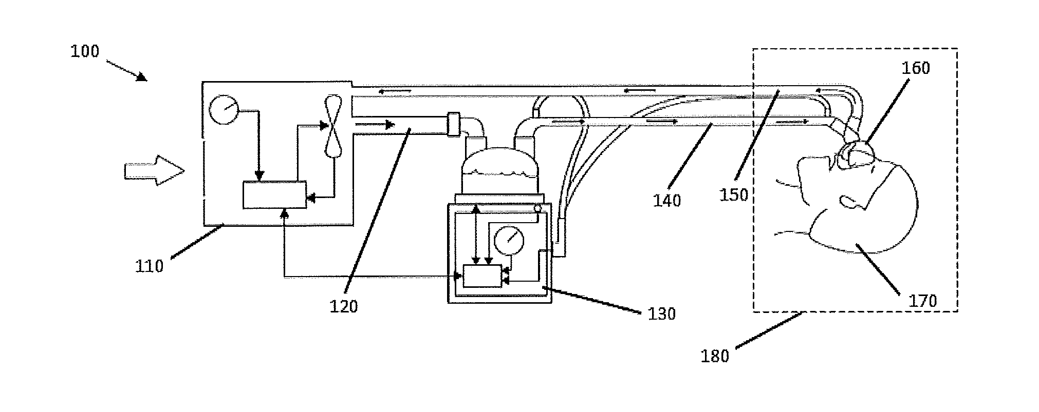
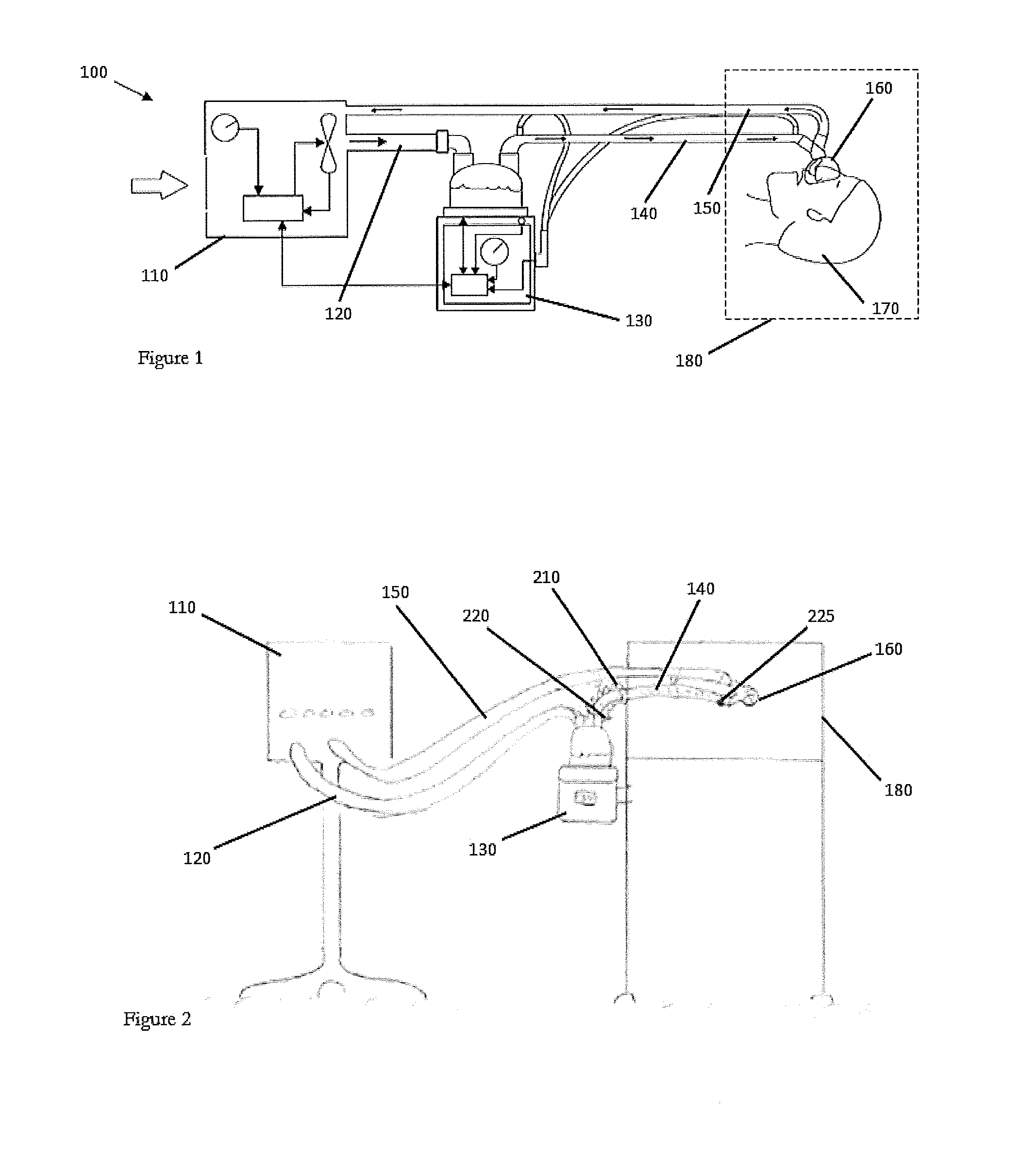
[0077]A gases source as herein described may refer to a source of respiratory gases for example, a ventilator, blower or wall source.

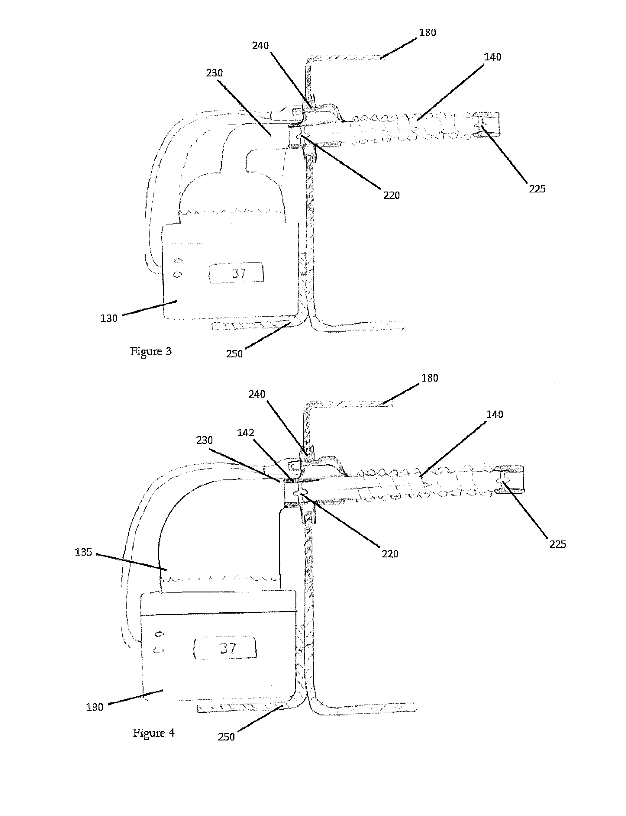
[0078]A humidification apparatus as herein described may refer to an apparatus that heats and humidifies respiratory gases. It may comprise a control system, a heating apparatus, and a humidification chamber. In some embodiments, the humidification apparatus may also comprise a gases source. In some embodiments, the gases source may be an integral part of the humidification apparatus.

[0079]A tube system may comprise both an inspiratory tube and an expiratory tube or, in some embodiments, the tube system may comprise only an inspiratory tube. The inspiratory tube may comprise multiple tubes. In some embodiments, at least one of the tubes or tube components may be heated.

[0080]A patient interface as herein described may refer to any component used to connect the tube system to the patient and may refer to a nasal cannula, nasal pillows, full face mask, o...


PUM


Abstract

A respiratory system provides conditioned respiratory gases to a patient within a controlled temperature environment. A humidification apparatus has an inspiratory tube that may extend to a patient interface. The inspiratory tube may have a reduced length. A thermal insulation component may insulate at least a portion of the inspiratory tube. As a result, less of the inspiratory tube may be exposed to the surrounding ambient environment, which may reduce condensate formation within the inspiratory tube and heat loss to the surrounding ambient environment. The humidification apparatus may be directly coupled to the controlled temperature environment.

Description

CROSS REFERENCE TO RELATED APPLICATIONS[0001]The present application claims priority benefit of the U.S. Provisional Application having the title DELIVERY OF RESPIRATORY GASES and Attorney Docket No. FPHCR.405PR and Ser. No. 61 / 895,084, filed on Oct. 24, 2013, which is hereby incorporated by reference in its entirety.BACKGROUND[0002]1. Technical Field[0003]The present disclosure generally relates to the delivery of humidified gases to a patient. More particularly, the present disclosure relates to a tube system for delivery of humidified gases to a patient within a controlled temperature environment.[0004]2. Description of the Related Art[0005]A humidification apparatus is used to provide heated and humidified respiratory gases to a patient via a patient interface. Respiratory gases delivered to a patient at 100% relative humidity and 37° C. mimic the transformation of air that occurs as the respiratory gases pass through the nose to the lungs. This may promote efficient gas exchang...

Claims


Application Information

Patent Timeline
IPC IPC(8): A61M16/08A61M16/16A61M16/10A61M16/00
CPCA61M16/0875A61M16/0003A61M16/161A61M16/109A61M2205/3334A61M2016/003A61M2205/3368A61M2205/3633A61M16/1095A61M16/16A61M2016/0039
Inventor ROBERTSON, NATALIE MAYHARWOOD, JONATHAN DAVIDANDRESEN, MICHAEL JOHN
Owner FISHER & PAYKEL HEALTHCARE LTD
Why Eureka
Try Eureka