
Method and Apparatus for Implantable Cardiac Lead Integrity Analysis

a technology of integrity analysis and implantable cardiac leads, which is applied in the field of electric therapeutic systems, can solve the problems of ineffective treatment, inability to accurately measure the impedance, and significant long-term reliability and safety of implantable cardiac leads, and achieve the effect of accurately measuring the impedance, without any risk of cardiac

Active Publication Date: 2016-09-22
LAMBDA NU TECH
View PDF4 Cites 13 Cited by
  • Summary
  • Abstract
  • Description
  • Claims
  • Application Information

AI Technical Summary

Benefits of technology

This patent provides methods and equipment to check the integrity of implantable cardiac leads. Instead of using traditional tests, this new method measures the movement of the conductor in relation to the outer insulation. This allows for the detection of small insulation failures and conductor migration. The advantages of this new method are that it can accurately measure impedance without affecting the heart and without any risk of cardiac effects from the very high frequency test signals.

Problems solved by technology

The long-term reliability and safety of implantable cardiac leads is a significant issue.
Conductor anomalies in the implantable cardiac leads for ICDs can result in morbidity and / or mortality from loss of pacing, inappropriate ICD shocks, and / or ineffective treatment of ventricular tachycardia or ventricular fibrillation.
Over time, this ETFE secondary insulating layer can (rarely) become abraded or damaged due one of various mechanisms.
Exposed conductors can also result in sensing of nonphysiological electrical signals, “noise”, if the exposed conductor is connected to a sensing electrode.
This results in incorrect detection of ventricular tachycardia or fibrillation (over-sensing) that may result in unnecessary painful shocks.
Even more worrisome, this problem may result in failed defibrillation shocks if the conductor is connected to the primary (distal) shock coil located in the right ventricle (RV).
Failed defibrillation shocks are particularly likely if the conductor to the RV shock coil abrades against the proximal shock coil in the superior vena cava (SVC) resulting in a short circuit when a shock is needed.
Such “under-the-coil” abrasions may occur without exteriorized cables so that they are undetectable by fluoroscopy, hence only detected when a shock is delivered.
It is not known how often or the extent to which early-stage failures of outer insulation may compromise sensing and / or defibrillation.
Further, exteriorized cables are not helpful in identifying inside-out abrasions occurring in Riata ST Optim™ and similar Durata leads™.
Under the shock-coils, coated leads are identical to similarly-designed leads without tubing, and they provide no additional protection against inside-out, cable-coil abrasion.
Presently, there is no way to detect inside-out abrasions in coated leads unless an electrical abnormality resulting in lead failure occurs.
In implantable cardiac leads, however, only one end of the conductor is generally accessible for testing purposes and changes in system impedance may be dominated by changes unrelated to conductor or implantable cardiac lead faults.
Unfortunately, none of these approaches provide a good solution for the unique problems of diagnosis and analysis of conductor anomalies due to migration and / or externalization.
At present, there is no testing available to determine if the conductors are migrating in the implantable cardiac lead body as there is no “ohmic” short or parasitic pathway.
Even when the conductors have become externalized and potentially abraded, it is not possible to detect this insulation failure as the small parasitic conduction through the insulation break is swamped by minor variations in the higher resistance of the measured current path including one or more defibrillation electrode coils or the pace-sense electrodes.
And, over-estimating the potential for implantable cardiac lead conductor anomalies has its own negative consequences, as a false positive may result in an unnecessary implantable cardiac lead replacement surgery, with corresponding expense and risk.

Method used


Image

  • Method and Apparatus for Implantable Cardiac Lead Integrity Analysis
  • Method and Apparatus for Implantable Cardiac Lead Integrity Analysis
  • Method and Apparatus for Implantable Cardiac Lead Integrity Analysis

Examples


Embodiment Construction

[0077]The embodiments of the present invention provide methods and apparatus for analyzing implantable cardiac leads to promote patient safety by evaluating possible issues with lead integrity, including conductor migration and / or externalization. The embodiments use an “imaginary” component of a high frequency transmission line impedance test having certain spectral changes that correspond to movements of the conductor to diagnose potential implantable cardiac lead integrity issues. This “imaginary impedance” test allows for the detection and identification of conductor migration and small insulation failures in implantable cardiac leads.

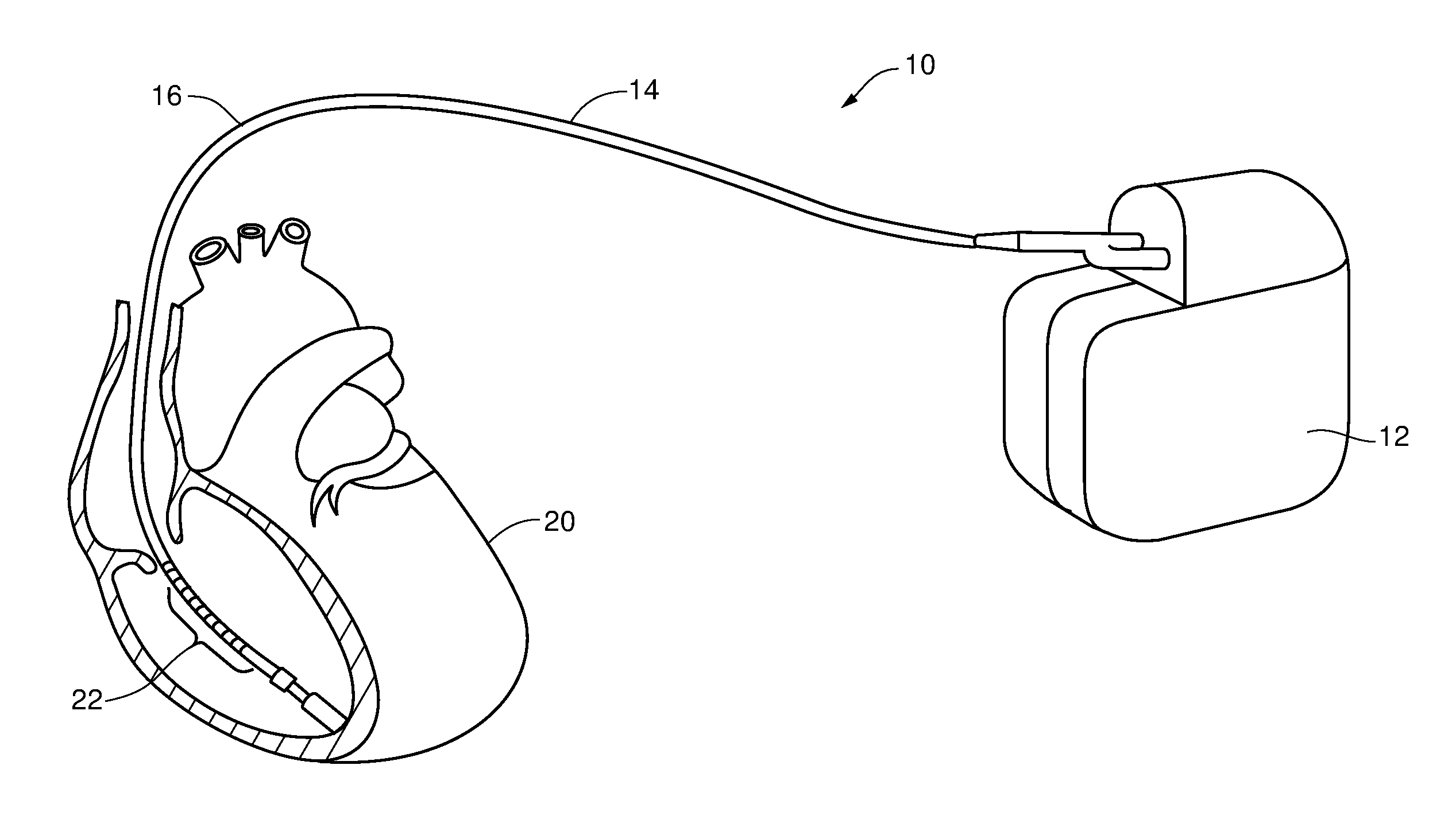
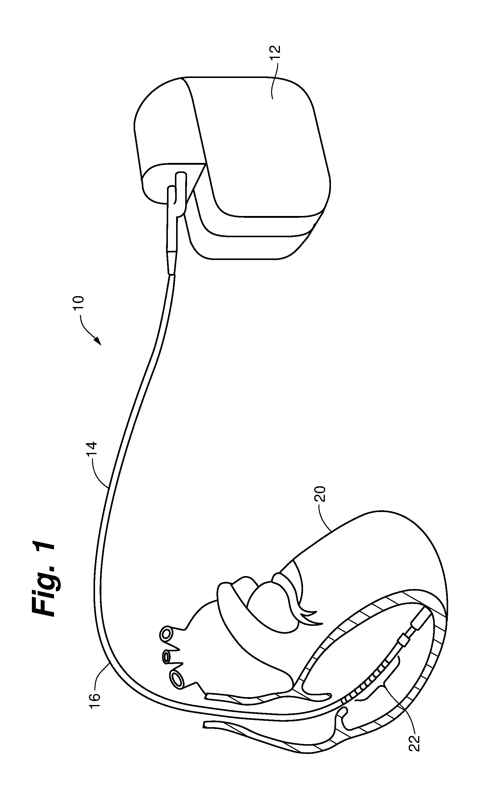
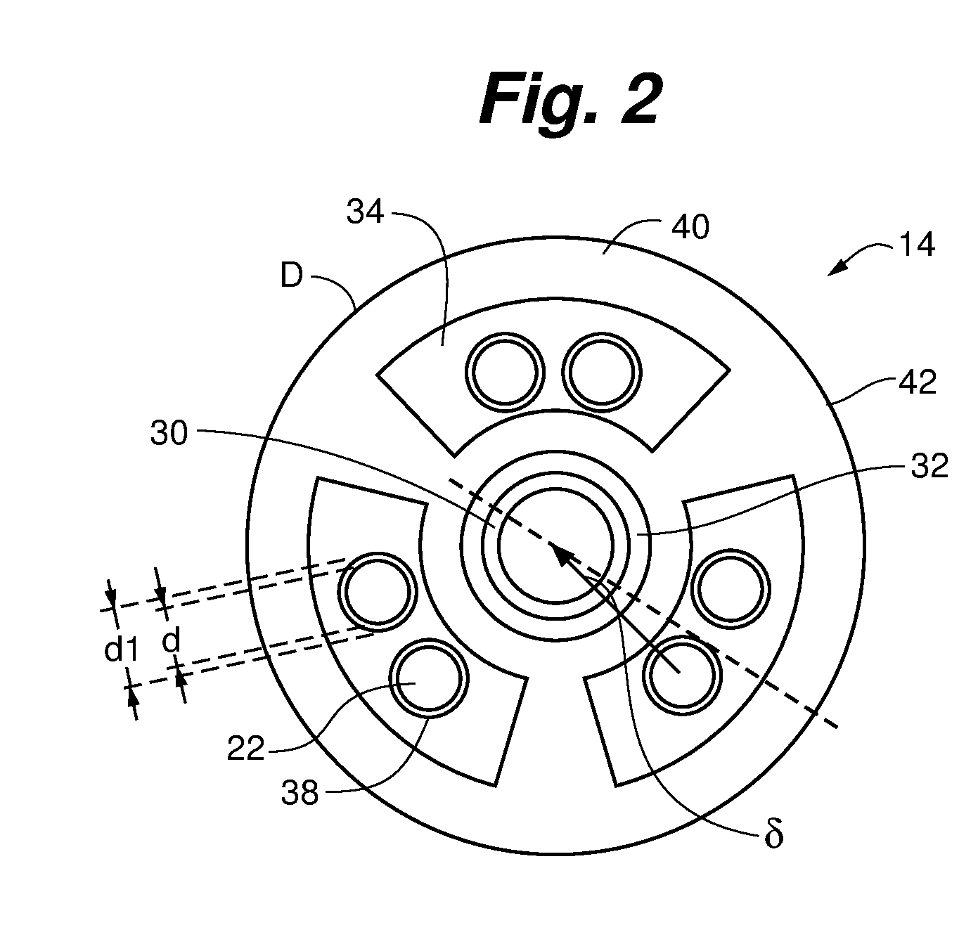
[0078]One application applies to diagnosis of conductor anomalies in implantable cardiac leads attached to an implantable medical device with a pulse generator, such as an ICD. Referring to FIG. 1, the implantable cardiac lead system 10 includes an implantable cardioverter defibrillator (ICD) pulse generator 12 and an implantable cardiac lead 14. T...


PUM


Abstract

The present invention relates, generally, to scientific and medical system methods for diagnosis of implantable cardioverter defibrillator (ICD) lead conductor anomalies, in particular conductor migration and externalization within an ICD implantable cardiac lead. The method uses an “imaginary” component of the high frequency transmission line impedance having certain spectral changes that correspond to movements of the conductor or an “imaginary impedance”. This allows the detection of conductor migration and small insulation failures.

Description

RELATED APPLICATION[0001]The present application claims the benefit of U.S. Provisional Application No. 61 / 733,713 filed Dec. 5, 2012, which is incorporated herein in its entirety by reference.FIELD OF THE INVENTION[0002]The present invention relates generally to electrical therapeutic systems for applying electrical therapy to patients for detecting and / or treating cardiac arrhythmias. More particularly, the invention relates to a method and apparatus for analyzing implantable cardiac leads to promote patient safety by evaluating possible issues with implantable cardiac lead integrity, including partial insulation failures, conductor migration, and / or externalization of conductors in multilumen leads.BACKGROUND[0003]Implantable cardioverter defibrillators (ICDs) are used to provide various types of therapy to treat cardiac arrhythmias in a patient, including, for example defibrillation. These devices typically consist of a hermetic housing implanted into a patient and connected to ...

Claims


Application Information

Patent Timeline
Patent Type & Authority Applications(United States)
IPC IPC(8): A61N1/08A61N1/39A61N1/05A61B5/276
CPCA61N1/08A61N1/0563A61N2001/083A61N1/3931A61N1/3956A61N1/056A61N1/3621A61N1/37A61N1/39622A61N1/3962
Inventor KROLL, MARK W.SWERDLOW, CHARLES D.
Owner LAMBDA NU TECH
Learn More