

Superheated steam treatment apparatus
a treatment apparatus and superheated technology, applied in the direction of lighting and heating apparatus, electric/magnetic/electromagnetic heating, energy industry, etc., can solve the problems of not being put into practical use and the production cost is greatly increased, and achieve the effect of efficient treatment of objects
- Summary
- Abstract
- Description
- Claims
- Application Information
AI Technical Summary
Benefits of technology
Problems solved by technology
Method used
Image

Examples
first embodiment
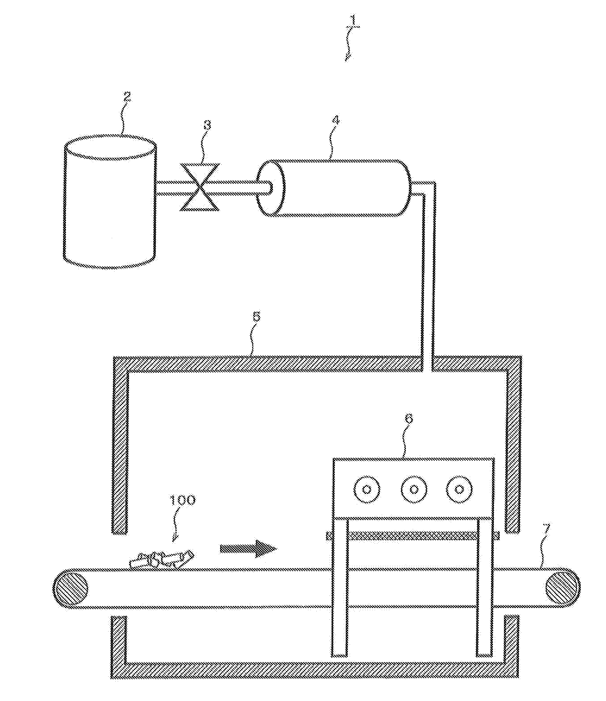
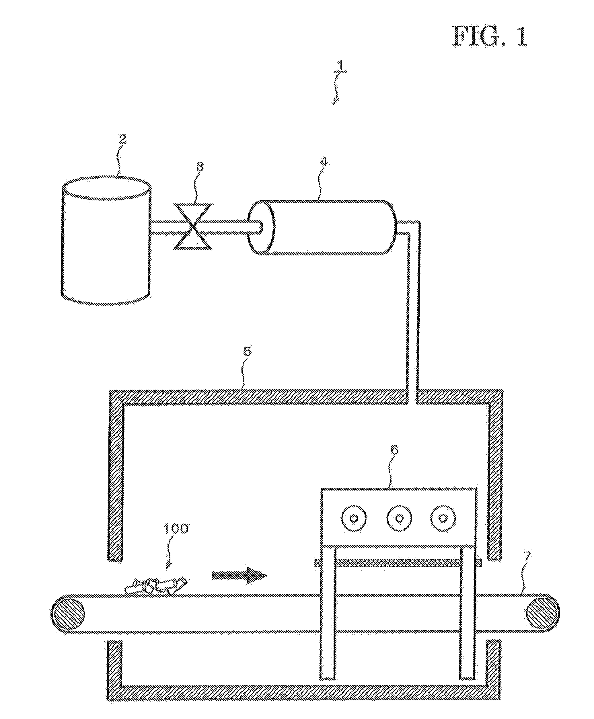
[0020]Hereinbelow, a superheated steam treatment apparatus 1 according to a first embodiment of the present invention will be described with reference to the drawings. FIG. 1 is a schematic view showing the configuration of the superheated steam treatment apparatus 1 according to the first embodiment of the present invention. The superheated steam treatment apparatus 1 comprises a boiler 2, a valve 3, an induction heating unit 4, a treatment chamber 5, a discharge treatment unit 6 and a belt conveyor 7.
[0021]The boiler 2 generates saturated steam by heating and boiling water supplied from a faucet, not shown. The water supplied to the boiler 2 is preferably clean water purified with a water purifier. The pressure of the saturated steam generated by the boiler 2 is set within the range of 1.1 to 1.6 atmospheres, preferably, 1.2 to 1.4 atmospheres. It is not desirable that the pressure of the saturated steam drops below 1.1 atmospheres, because it reduces the amount of superheated ste...
second embodiment
[0045]FIG. 6 shows the configuration of a superheated steam treatment apparatus 1 according to a second embodiment of the present invention. This embodiment is characterized by not having the belt conveyer 7 as in the first embodiment, so that the object 100 should be placed immediately below the opposite electrode 65 in the discharge treatment unit 6. It should be noted that since the other components are the same as those in the foregoing first embodiment except for the changes resulting from the removal of the belt conveyor 7, the explanation thereof will be omitted hereinbelow.
[0046]Hereinbelow, the treatment process by the superheated stream treatment apparatus 1 according to the second embodiment will be described with reference to the flow chart shown in FIG. 7.
[0047]Prior to the treatment, the object 100 is placed immediately below the opposite electrode 65 in the discharge treatment unit 6. At the start of the treatment, saturated steam at 100° C. or more, for example, at 1...
example 1
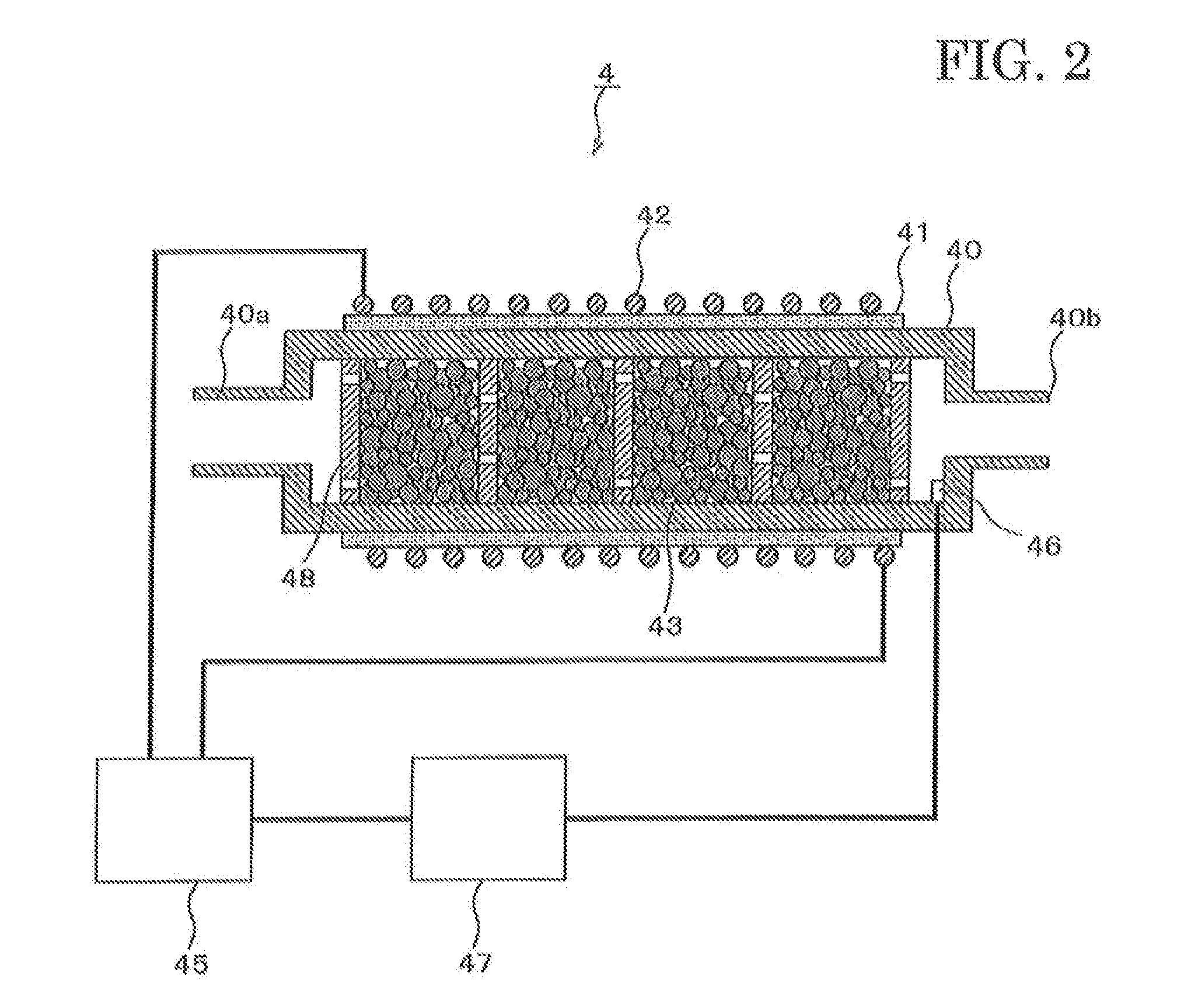
[0051]For the induction heating unit, used was a container made of SUS430 and having an outside diameter of 120 mm φ, a thickness of 5 mm and a length of 250 mm. A 10 mm space in the moving direction of the saturated steam was formed with a first partition wall disposed at the end thereof. Other partition walls were disposed at intervals of 10 mm in the moving direction of the saturated steam. Each partition wall had a thickness of 5 mm, and concentric grooves having a width of 2 mm, a depth of 2 mm and a radius of 90 mm, 70 mm or 50 mm were formed in its surface along the circumference. At the bottom of the groove, 2 mm φ through-holes are formed at regular intervals. Pellets (induction heating members 43) were 5 mm φ particles of SUS430, filling up each space. The high-frequency power source for the induction heating unit was such that an input voltage being a commercial power supply of 200 VAC, 60 Hz and 20 kW was converted to a high frequency high voltage of 20 kHz by an inverte...
PUM
 Abstract
Description
Claims
Application Information