Eureka AIR delivers breakthrough ideas for toughest innovation challenges, trusted by R&D personnel around the world.

Sparse modulation for robust signaling and synchronization

a signaling and synchronization technology, applied in the field of signal communication, can solve the problems of limiting the ability to find and read code, increasing the cost of scanners, slowing down code reading, etc., and achieve the effect of improving data capacity

Active Publication Date: 2016-09-22
DIGIMARC CORP
View PDF2 Cites 77 Cited by
  • Summary
  • Abstract
  • Description
  • Claims
  • Application Information

AI Technical Summary

Benefits of technology

This patent describes a way to make codes that can be applied to objects using various printing techniques. These codes are not designed to be aesthetically pleasing or to be woven into other imagery. Code placement is often at a dedicated location on the object, which can slow down reading and increase risk of injury. The patent proposes a solution by generating signals that can be embedded within host signals and using flexible methods to achieve good perceptual quality and data capacity. These signals can be detected and read quickly, even when placed at inconspicuous locations on objects.

Problems solved by technology

Nevertheless, placing the code at a dedicated location limits the ability to find and read the code.
This placement of the code tends to slow down code reading or increase scanner cost by requiring additional components to capture multiple views of an object.
It also increases risk of injury due to the need for workers to re-position the object to scan the code for auto-identification.
Obviously, this undermines the theoretical speed and reliability advantages of auto-identification.
There are, of course, limits to the extent to which this payload can be inserted in existing image or audio (the host signal) without impacting the perceptual quality of the host.
This is a challenging metric, as it has a significant subjective component.
The sparse signal has minimal impact on visual quality due to its sparse arrangement.
However, the trade-off for applications like automatic object identification is that more sophistication is required in the data signaling methodology to ensure that the data carried within the sparse signal may be reliably and efficiently recovered in many different and challenging environments.
These include computational efficiency, power consumption, memory consumption, memory bandwidth, use of network bandwidth, cost of hardware circuitry or programmable processors / circuitry, cost of designing and integrating encoders and decoders within signal transmitter and receiver, equipment, etc.
For example, some encoding schemes may provide optimized encoding or decoding, but may not be applicable because they are too slow for encoding or decoding in real time, e.g., as the host signal is being transmitted, received, updated, or being processed with multiple other signal processing operations concurrently.
Sparse signaling is particularly challenging in that the sparse nature of the signal provides less opportunity to include signal for payload and robustness.

Method used


Image

  • Sparse modulation for robust signaling and synchronization
  • Sparse modulation for robust signaling and synchronization
  • Sparse modulation for robust signaling and synchronization

Examples


Embodiment Construction

Signal Encoder and Decoder

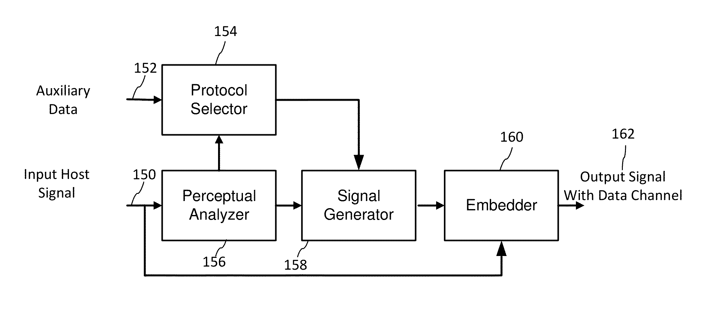
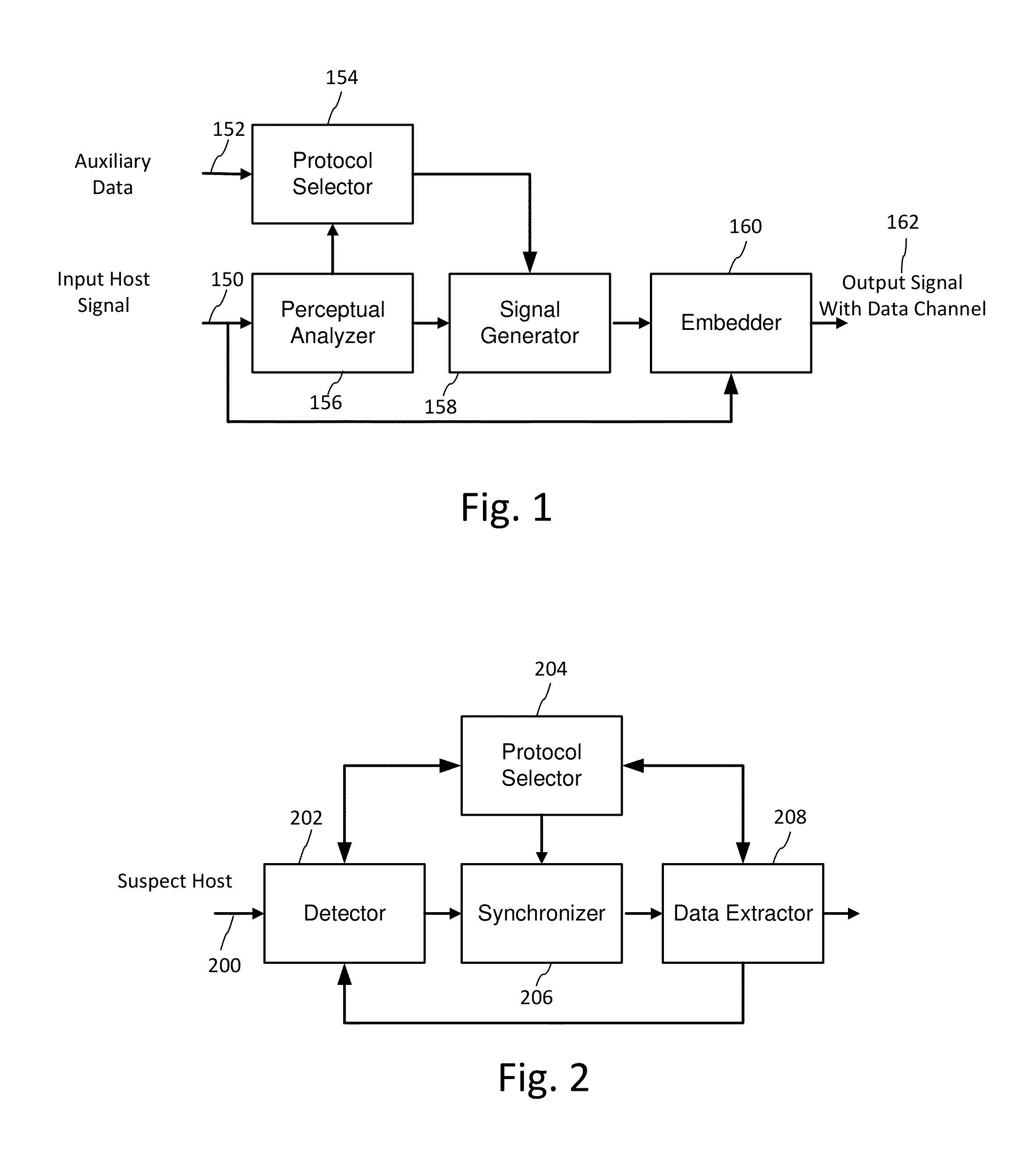
[0040]FIG. 1 is a block diagram of a signal encoder for encoding a sparse signal. FIG. 2 is a block diagram of a compatible signal decoder for extracting a payload from a sparse signal encoded on an object or within an image displayed on a video display.

[0041]Encoding and decoding is typically applied digitally, yet the signal is expected to survive digital to analog transformation and analog to digital transformation. For example, the encoder generates an image including the sparse signal that is converted to a rendered form, such as a printed image, displayed image or video. We use the term “printing” to encompass a wide variety of marking technologies, including engraving, etching, stamping, etc. as there are a variety of ways to impart the image carrying the sparse signal to an object. Prior to decoding, a receiving device captures an image or stream of images of the object through its image sensor such as a camera (e.g., CMOS or CCD), and converts it t...


PUM


Abstract

Sparse signal modulation schemes encode a data channel on a host image in a manner that is robust, flexible to achieve perceptual quality constraints, and provides improved data capacity. The host image is printed by any of a variety of means to apply the image, with sparse signal, to an object. After image capture of the object, a decoder processes the captured image to detect and extract data modulated into the sparse signal. The sparse signal may incorporate implicit or explicit synchronization components, which are either formed from the data signal or are complementary to it.

Description

RELATED APPLICATION DATA[0001]This application claims benefit of U.S. Provisional Patent Application No. 62 / 136,146, filed Mar. 20, 2015. The 62 / 136,146 application is hereby incorporated herein by reference in its entirety.TECHNICAL FIELD[0002]The invention relates to signal communication in noisy environments, and in particular to robust signal communication within host media signals, such as digital watermarking.BACKGROUND AND SUMMARY[0003]Many approaches have been developed for encoding machine readable information on objects. Perhaps the most well-known technique is the ubiquitous barcode. Over the years, various barcode types have been created, which differ significantly from the name-sake pattern of dark linear bars on a lighter background. Now, the term barcode has been used to encompass machine symbols in various shapes, sizes, patterns and colors.[0004]These types of codes were primarily developed to be reliable data carriers that could be applied with a wide array of prin...

Claims


Application Information

Patent Timeline
IPC IPC(8): G06T1/00H04N19/467H04N19/124
CPCG06T1/0021H04N19/467H04N19/124
Inventor HOLUB, VOJTECHHAAGA, DONALDSHARMA, RAVI K.
Owner DIGIMARC CORP
Why Eureka
Eureka Blog
Learn More