Multi-gap rotating electric machine
- Summary
- Abstract
- Description
- Claims
- Application Information
AI Technical Summary
Benefits of technology
Problems solved by technology
Method used
Image


Examples
first embodiment
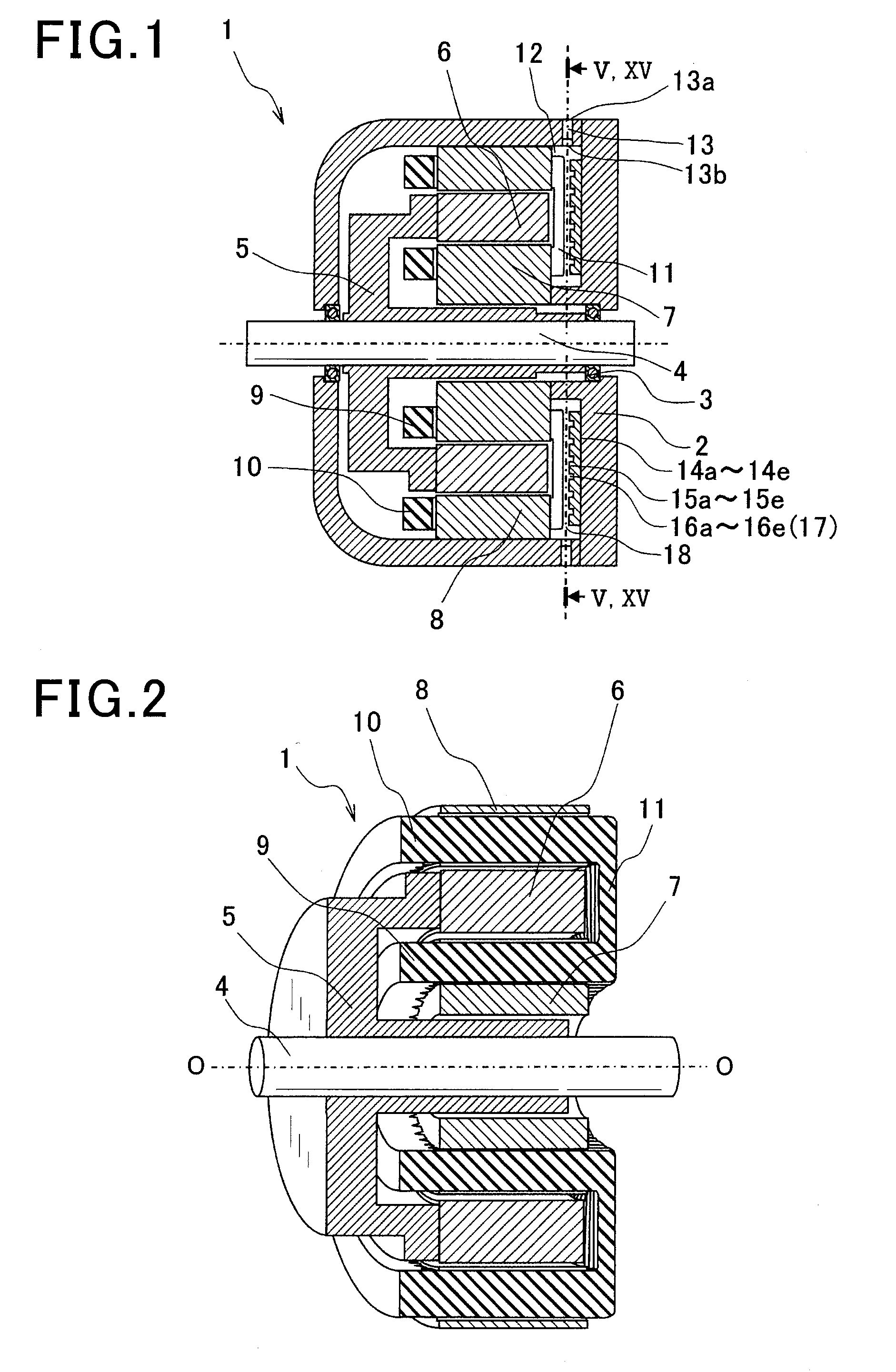
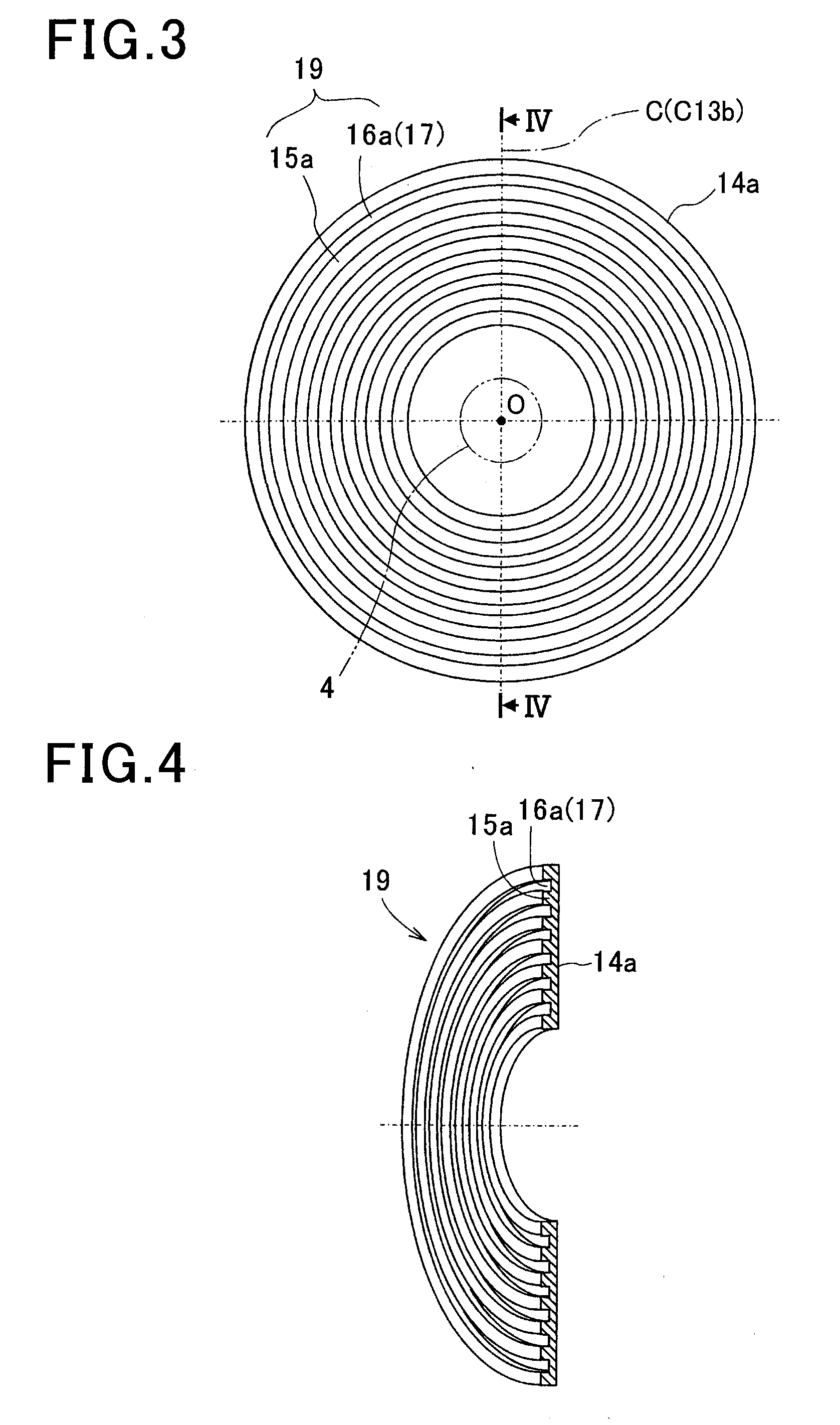
[0045]The cooling oil flow adjustment member 14a according to the first embodiment will be described with reference to FIGS. 3-6.
[0046]In the present embodiment, the cooling oil flow adjustment member 14a has a plurality of cooling oil guide channels 17 formed of the plurality of protrusions 15a and the plurality of recesses 16a on the uneven surface 19. The protrusions 15a and the recesses 16a are shaped in circular rings concentric with the rotating shaft 4. Accordingly, the cooling oil guide channels 17 extend in the circumferential direction of the rotating shaft 4 which is different from the extending directions of the side stator coil 11 (i.e., radial directions of the rotating shaft 4). Moreover, when viewed along a central axis (or longitudinal axis) O of the rotating shaft 4, on an upper half of the uneven surface 19 which is located above the central axis O of the rotating shaft 4, the cooling oil guide channels 17 spread from a reference line C to both sides of the refere...
second embodiment
[0050]The cooling oil flow adjustment member 14b according to the second embodiment will be described with reference to FIGS. 7 and 8.
[0051]In the present embodiment, the cooling oil flow adjustment member 14b has a plurality of cooling oil guide channels 17 formed of the plurality of protrusions 15b and the plurality of recesses 16b on the uneven surface 19. The protrusions 15b and the recesses 16b are shaped in square rings concentric with the rotating shaft 4. Accordingly, the cooling oil guide channels 17 extend straight in each of a plurality of directions different from the extending directions of the side stator coil 11 (i.e., radial directions of the rotating shaft 4). Moreover, when viewed along the central axis O of the rotating shaft 4, on the upper half of the uneven surface 19 which is located above the central axis O of the rotating shaft 4, the cooling oil guide channels 17 spread from the vertical reference line C to both sides of the reference line C while extending...
third embodiment
[0054]The cooling oil flow adjustment member 14c according to the third embodiment will be described with reference to FIGS. 9 and 10.
[0055]In the present embodiment, the cooling oil flow adjustment member 14c has a plurality of cooling oil guide channels 17 formed of the plurality of protrusions 15c and the plurality of recesses 16c on the uneven surface 19. The protrusions 15c and the recesses 16c are shaped in elliptical rings concentric with the rotating shaft 4. Accordingly, the cooling oil guide channels 17 extend in a curved manner in directions different from the extending directions of the side stator coil 11 (i.e., radial directions of the rotating shaft 4). Moreover, when viewed along the central axis O of the rotating shaft 4, on the upper half of the uneven surface 19 which is located above the central axis O of the rotating shaft 4, the cooling oil guide channels 17 spread from the vertical reference line C to both sides of the reference line C while extending downward...
PUM
 Abstract
Description
Claims
Application Information
 - R&D
- Intellectual Property
- Life Sciences
- Materials
- Tech Scout
- Unparalleled Data Quality
- Higher Quality Content
- 60% Fewer Hallucinations
Browse by: Latest US Patents, China's latest patents, Technical Efficacy Thesaurus, Application Domain, Technology Topic, Popular Technical Reports.
© 2025 PatSnap. All rights reserved.Legal|Privacy policy|Modern Slavery Act Transparency Statement|Sitemap|About US| Contact US: help@patsnap.com