Ultrasound signal processing device, ultrasound diagnostic device

Active Publication Date: 2016-09-29
KONICA MINOLTA INC
View PDF2 Cites 10 Cited by
  • Summary
  • Abstract
  • Description
  • Claims
  • Application Information

AI Technical Summary

Benefits of technology

[0009]In view of such problems, the present disclosure provides an ultrasound signal processing device and an ultrasound diagnostic device equipped with such an ultrasound signal processing device that achieve an increase in frame rate

Problems solved by technology

Due to this, one ultrasound transmission event generates only one or a few acoustic line signals along the central axis of the transmitted ultrasound beam, and thus, reflected ultrasound is not utilized in an ef

Method used


Image

  • Ultrasound signal processing device, ultrasound diagnostic device
  • Ultrasound signal processing device, ultrasound diagnostic device
  • Ultrasound signal processing device, ultrasound diagnostic device

Examples


Example

Embodiment 1

Overall Structure

[0049]The following describes an ultrasound diagnostic device 100 pertaining to embodiment 1, with reference to the accompanying drawings.

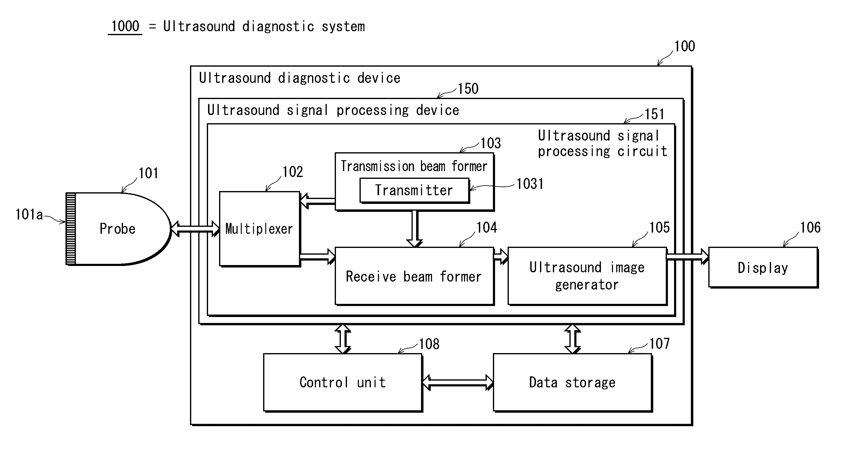
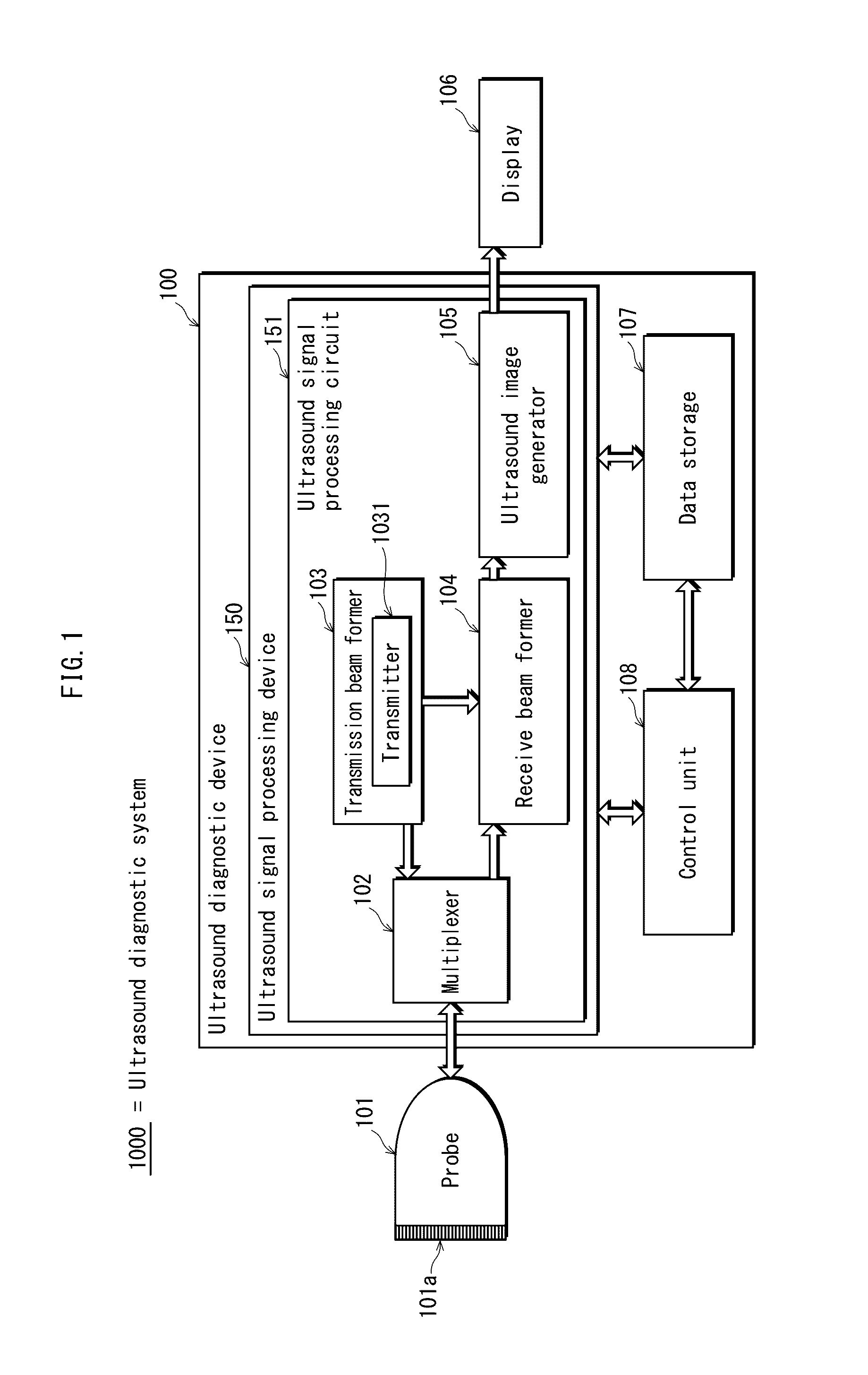
[0050]FIG. 1 illustrates functional blocks of an ultrasound diagnostic system 1000 pertaining to embodiment 1. As illustrated in FIG. 1, the ultrasound diagnostic system 1000 includes: a probe 101; the ultrasound diagnostic device 100; and a display unit 106. The probe 101 includes a plurality of transducer elements 101a. Each of the transducer elements 101a is capable of transmitting ultrasound towards the subject and receiving reflected ultrasound (echo signals). The ultrasound diagnostic device 100 causes the probe 101 to perform transmission / reception of ultrasound, and generates an ultrasound image based on signals output from the probe 101. The display unit 106 displays the ultrasound image on any display device provided thereto. The probe 101 and the display unit 106 are separately connectable to the ultrasound ...

Example

Embodiment 2

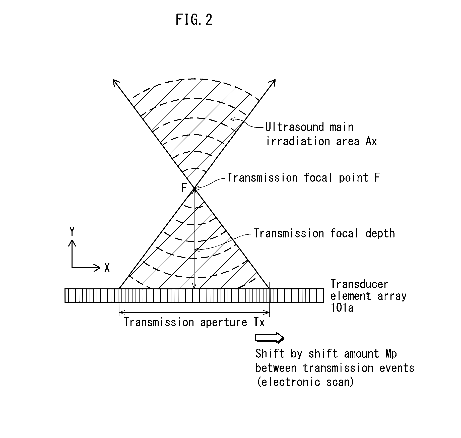
[0144]The ultrasound diagnostic apparatus 100 includes the delay-and-sum processor 1041, which generates sub-frame acoustic line signals, and the synthesizer 1140, which combines the sub-frame acoustic signals to generate a frame acoustic line signal. Here, it should be noted that in embodiment 1, no distinction is made between measurement points inside the ultrasound main irradiation area Ax and measurement points outside the ultrasound main irradiation area Ax in the generation of sub-frame acoustic line signals. However, acoustic line signals generated from measurement points outside the ultrasound main irradiation area Ax, when compared with acoustic line signals generated from measurement points inside the ultrasound main irradiation area Ax, have lower spatial resolution and lower signal S / N ratio. This is since, as already described above, amplitude of transmitted ultrasound decreases and phase difference of transmitted ultrasound increases outside the ultrasound ...


PUM


Abstract

An ultrasound signal processing device: performing events involving transmitting ultrasound towards a subject; receiving ultrasound reflection from the subject in response to each event; and generating a frame signal from sub-frame signals generated based on the ultrasound reflection. The device, in each event, causes a transmission aperture to transmit ultrasound focusing in the subject. A transmission aperture for one event differs in position, in a transducer element array direction, from a transmission aperture for a previous event by a shift amount of at least twice a transducer element width. The device, for each event, sets a target area which includes a position where transmitted ultrasound focuses and whose width in the transducer element array direction, at a depth where the transmitted ultrasound focuses, is equal to or greater than the shift amount. The device generates a sub-frame signal covering measurement points included in the target area.

Description

[0001]This application is based on an application No. 2015-066483 filed in Japan, the contents of which are hereby incorporated by reference.BACKGROUND OF THE INVENTION[0002](1) Field of the Invention[0003]The present disclosure is related to an ultrasound signal processing device, and an ultrasound diagnostic device equipped with the ultrasound signal processing device. In particular, the present disclosure relates to receive beam forming in an ultrasound signal processing device.[0004](2) Description of the Related Art[0005]Typically, an ultrasound diagnostic device transmits ultrasound towards the inside of a subject via an ultrasound probe (referred to in the following as a “probe”), and receives reflected ultrasound (an echo) via the probe. The reflected ultrasound is generated within the subject due to tissues in the subject having different acoustic impedances. Further, an ultrasound diagnostic device generates an ultrasound tomographic image based on electric signals acquire...

Claims


Application Information

Patent Timeline
IPC IPC(8): A61B8/08A61B8/00G06F19/00
CPCA61B8/5207A61B8/4483G06F19/321A61B8/4444A61B8/5269A61B8/54G01S7/52095G01S15/8997G01S7/52046G01S7/52047G01S15/8927G16H50/20G16H30/20
Inventor TSUSHIMA, MINEO
Owner KONICA MINOLTA INC
Why Eureka
Try Eureka