Spinal Implant Assembly

a technology of spine and implant, applied in the field of spine implant assembly, can solve the problems of limiting the range of motion of the spine, unable to stably receive the bone screw, and the complex structure of the spine column, and achieve the effect of improving the stability of the anchorag

Inactive Publication Date: 2016-09-29
FITZBIONICS
View PDF46 Cites 21 Cited by
  • Summary
  • Abstract
  • Description
  • Claims
  • Application Information

AI Technical Summary

Benefits of technology

[0028]Preferably the head component has a shank portion insertable within the hollow bore of the body component, the shank portion of the head component being shorter in length than the hollow bore of the body component such that with the shank...

Problems solved by technology

In its entirety, the spinal column is highly complex in that it houses and protects critical elements of the nervous system which have innumerable peripheral nerves and arterial and venous bodies in close proximity.
Genetic or developmental irregularities, trauma, chronic stress, tumors, and disease, however, can result in spinal pathologies which either limit this range of motion, or which threaten the critical elements of the nervous system housed within the spinal column.
A problem with these stabilisation systems is that parts of the vertebra cannot stably receive a bone...

Method used


Image

  • Spinal Implant Assembly
  • Spinal Implant Assembly
  • Spinal Implant Assembly

Examples


Embodiment Construction

[0049]The present embodiments represent currently the best ways known to the applicant of putting the invention into practice. But they are not the only ways in which this can be achieved. They are illustrated, and they will now be described, by way of example only.

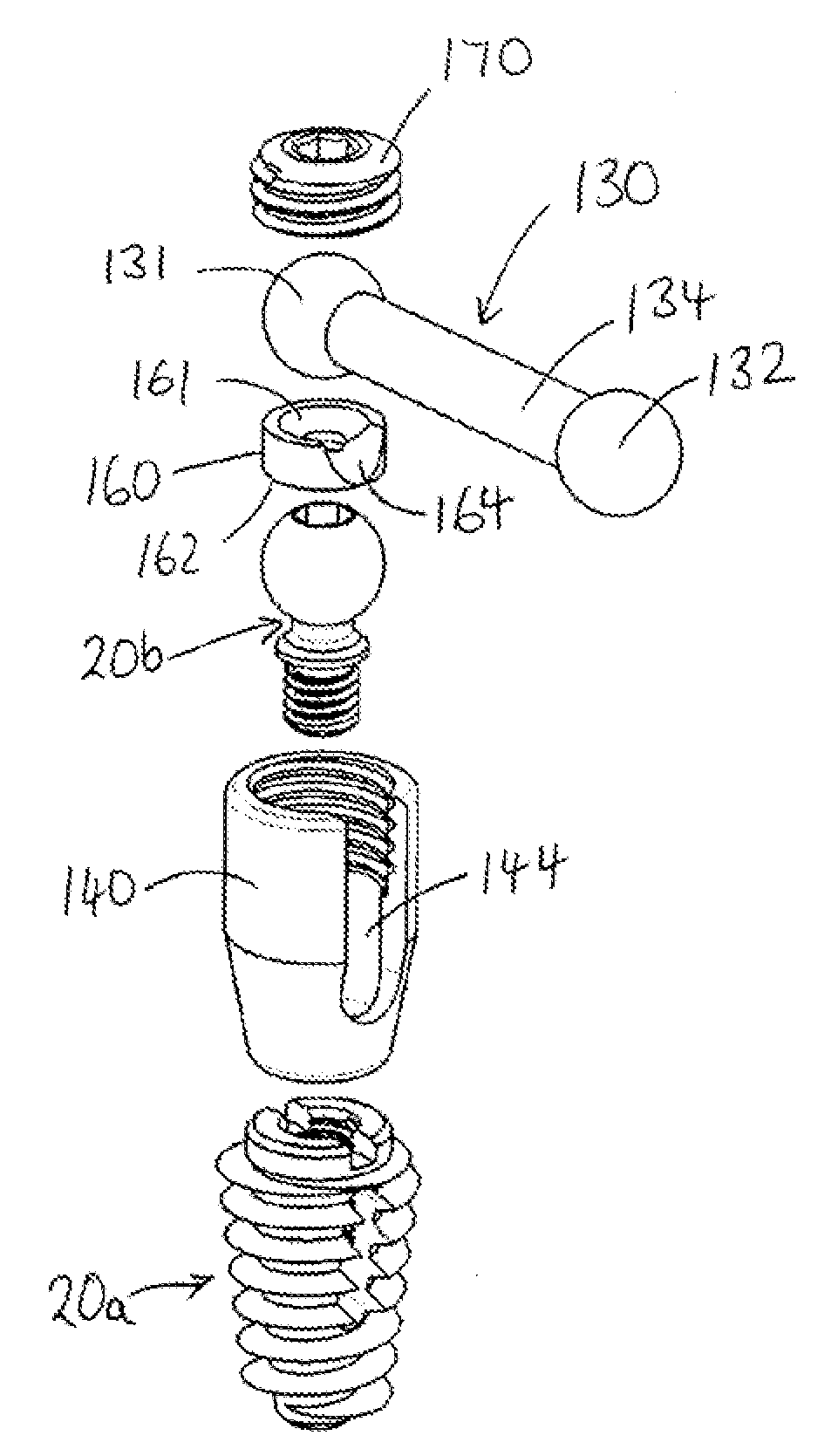
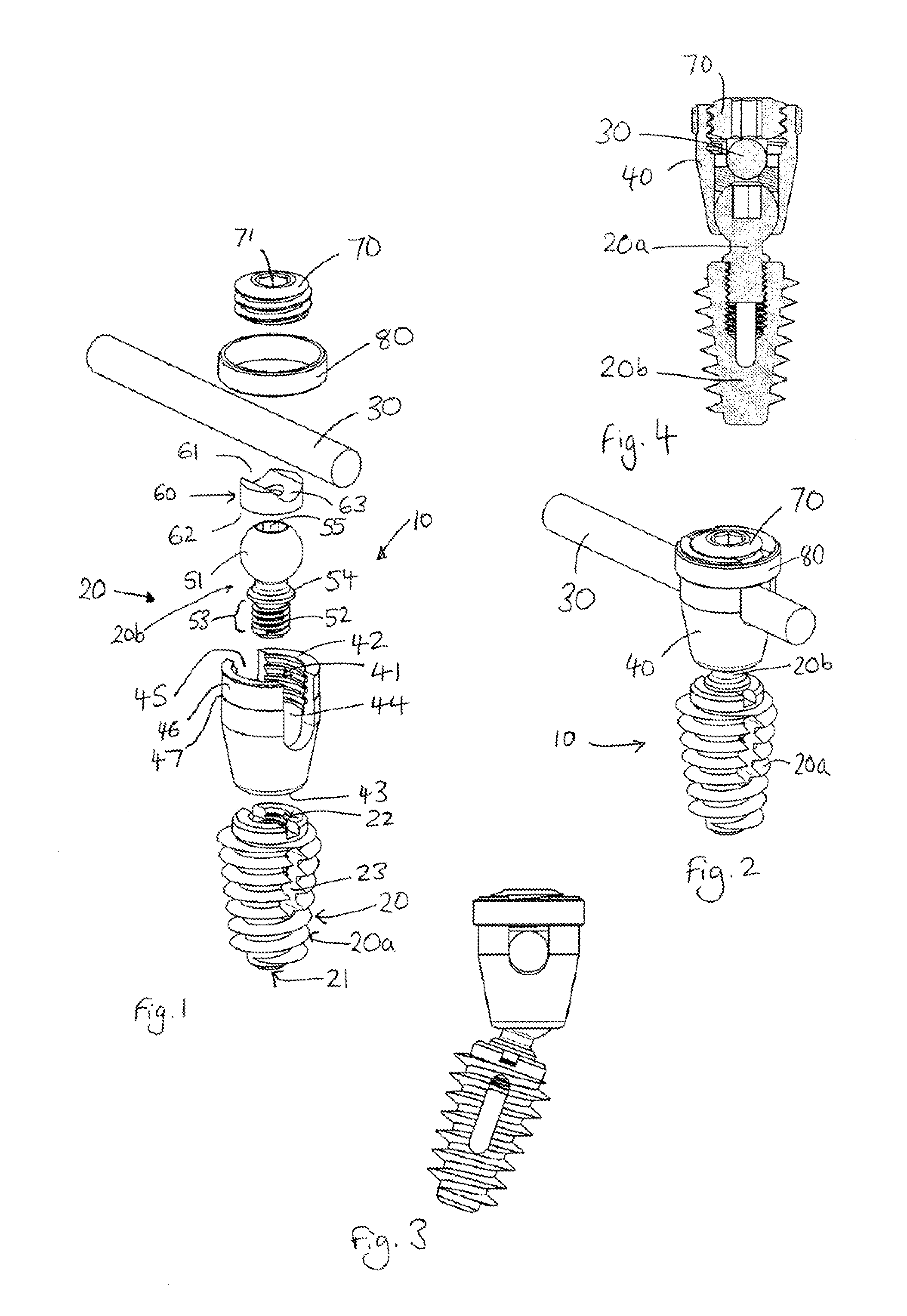
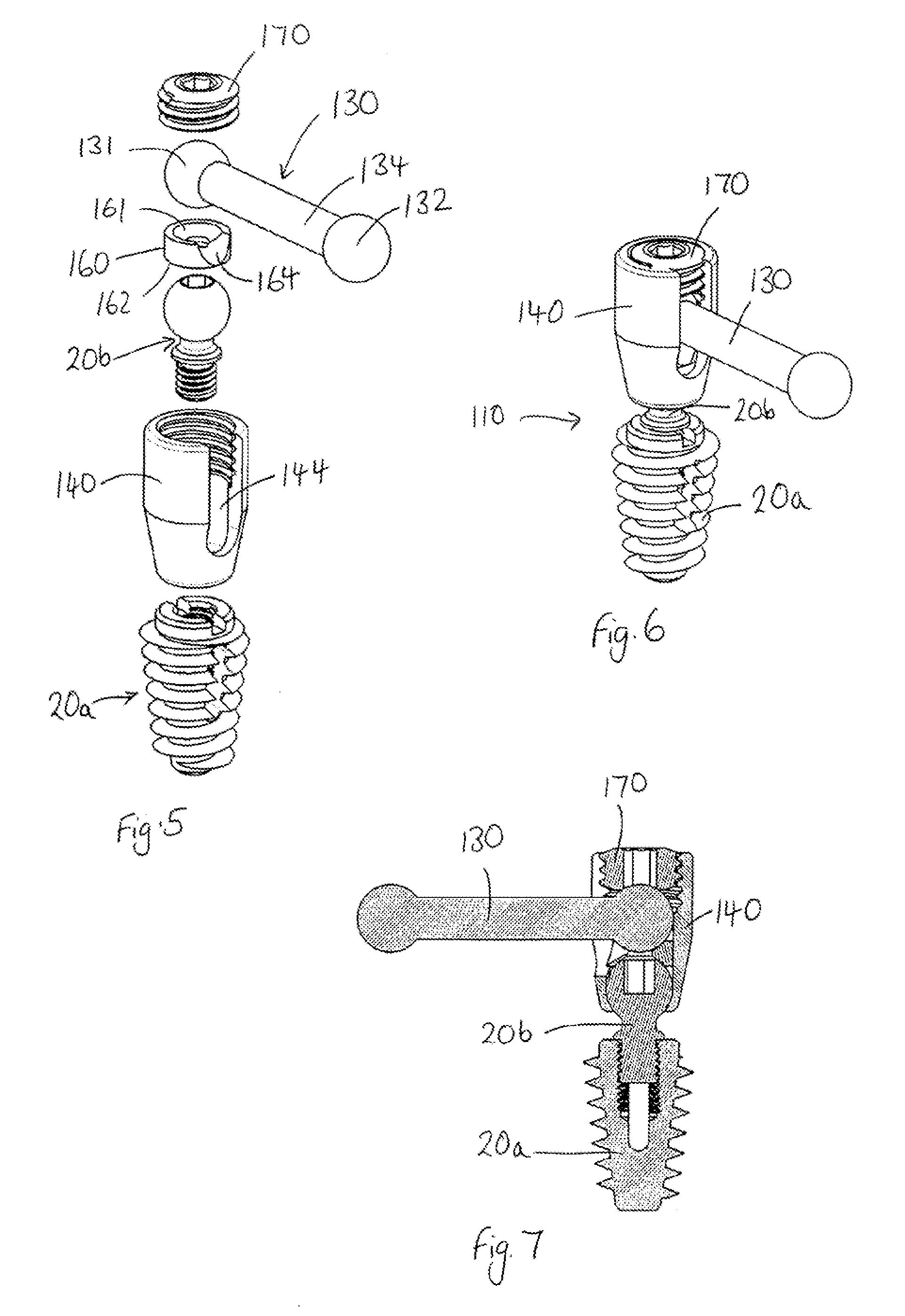
[0050]Referring to FIG. 1, this shows a spinal implant assembly 10 according to a first embodiment. The assembly can be used to fuse two or more vertebra together, in order and to provide stabilisation of the spine. The assembly 10 comprises an intervertebral device 20, an elongate member 30 and a coupling body 40. The assembly is designed such that the intervertebral device 20 can be coupled for multiaxial positioning relative to the coupling body 40 and elongate rod 30.

[0051]The intervertebral device 20 comprises a body component 20a and a head component 20b. The body component 20a of the intervertebral device is configured for installation in a spinal disc space between any two vertebrae of a subject, including the spa...


PUM


Abstract

A spinal implant assembly comprising an intervertebral device configured to be installed in a spinal disc space, the intervertebral device having a head component and a body component, the spinal implant assembly further comprising a coupling body for coupling the head component of the intervertebral device and an elongate member, the coupling body and head component each having a longitudinal axis, wherein the head component can be received by the coupling body with its longitudinal axis at a selected angle within a predetermined range of angles relative to the longitudinal axis of the coupling body.

Description

FIELD OF THE INVENTION[0001]The invention relates to a spinal implant assembly. More specifically the invention relates to assemblies with parts for implantation into intervertebral space between adjacent vertebrae of the spine.BACKGROUND TO THE INVENTION[0002]The spine or vertebral column comprises a plurality of separate vertebrae. The vertebrae are movable relative to one another, and separated from one another by fibrocartilage called inter-vertebral discs.[0003]In its entirety, the spinal column is highly complex in that it houses and protects critical elements of the nervous system which have innumerable peripheral nerves and arterial and venous bodies in close proximity. In spite of these complexities, the spine is a highly flexible structure, capable of a high degree of curvature and twist through a wide range of motion. The intervertebral discs provide mechanical cushion between adjacent vertebrae. Genetic or developmental irregularities, trauma, chronic stress, tumors, and...

Claims


Application Information

Patent Timeline
IPC IPC(8): A61B17/70
CPCA61B17/7032A61B2017/00526A61B17/7002A61B17/7005A61B17/7037A61B17/864A61B17/8685A61B17/70A61B17/704A61F2/446A61B34/10A61B2034/108A61F2/30942A61F2002/30405A61F2002/30433A61F2002/30622A61F2002/449
Inventor FITZPATRICK, NOEL
Owner FITZBIONICS
Why Eureka
Try Eureka