Device and method for loading implant into delivery system

a technology of delivery system and device, applied in the field of devices and methods for loading implants into delivery systems, can solve problems such as complicated operations and achieve the effects of reducing surgery time, facilitating smooth operations, and facilitating and quick operations

Active Publication Date: 2016-09-29
SHANGHAI MICROPORT CARDIOFLOW MEDTECH CO LTD
View PDF5 Cites 59 Cited by
  • Summary
  • Abstract
  • Description
  • Claims
  • Application Information

AI Technical Summary

Benefits of technology

[0015]According to the present invention, the loading of the implant is accomplished with only three components of the device which are distinct in appearance without causing confusions, i.e., the guide cap, the guider and the guiding tube. Additionally, the slight shrinkage in radial dimension of the guider at the middle portion enables the valve prosthesis to be capsuled therein without escaping and causing interruptions. Moreover, the guiding tube, that has a relatively long tapered tubular section at one end, or is implemented completely as a tapered tube, provides protection to the catheter of the delivery system and al

Problems solved by technology

This device, however, requires complicat

Method used


Image

  • Device and method for loading implant into delivery system
  • Device and method for loading implant into delivery system
  • Device and method for loading implant into delivery system

Examples


Embodiment Construction

[0029]Exemplary embodiments of the present invention will be described below with reference to the accompanying drawings. While various details of embodiments of the present invention are set forth in the following detailed description to facilitate understanding, they are to be construed as illustrative only. Accordingly, it is to be appreciated by those of ordinary skill in the art that the embodiments disclosed herein are susceptible to various alterations and modifications without departing from the scope and sprit of the present invention. Further, for the sake of clarity and conciseness, description of some well-known functions and structures is omitted.

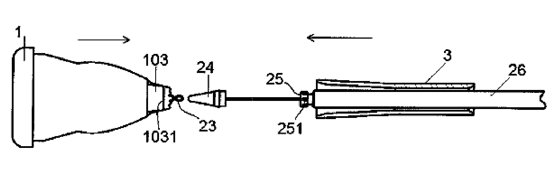
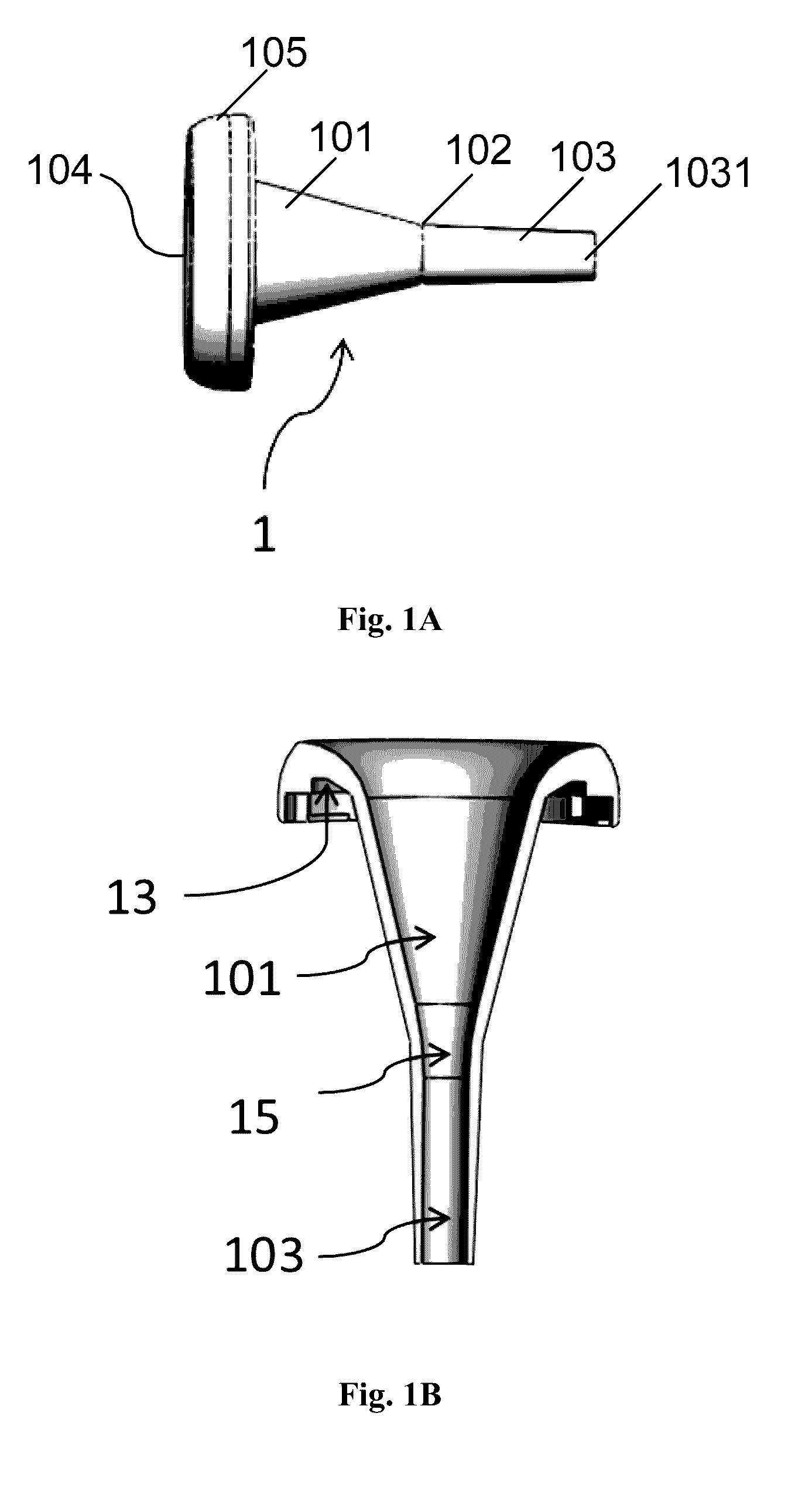
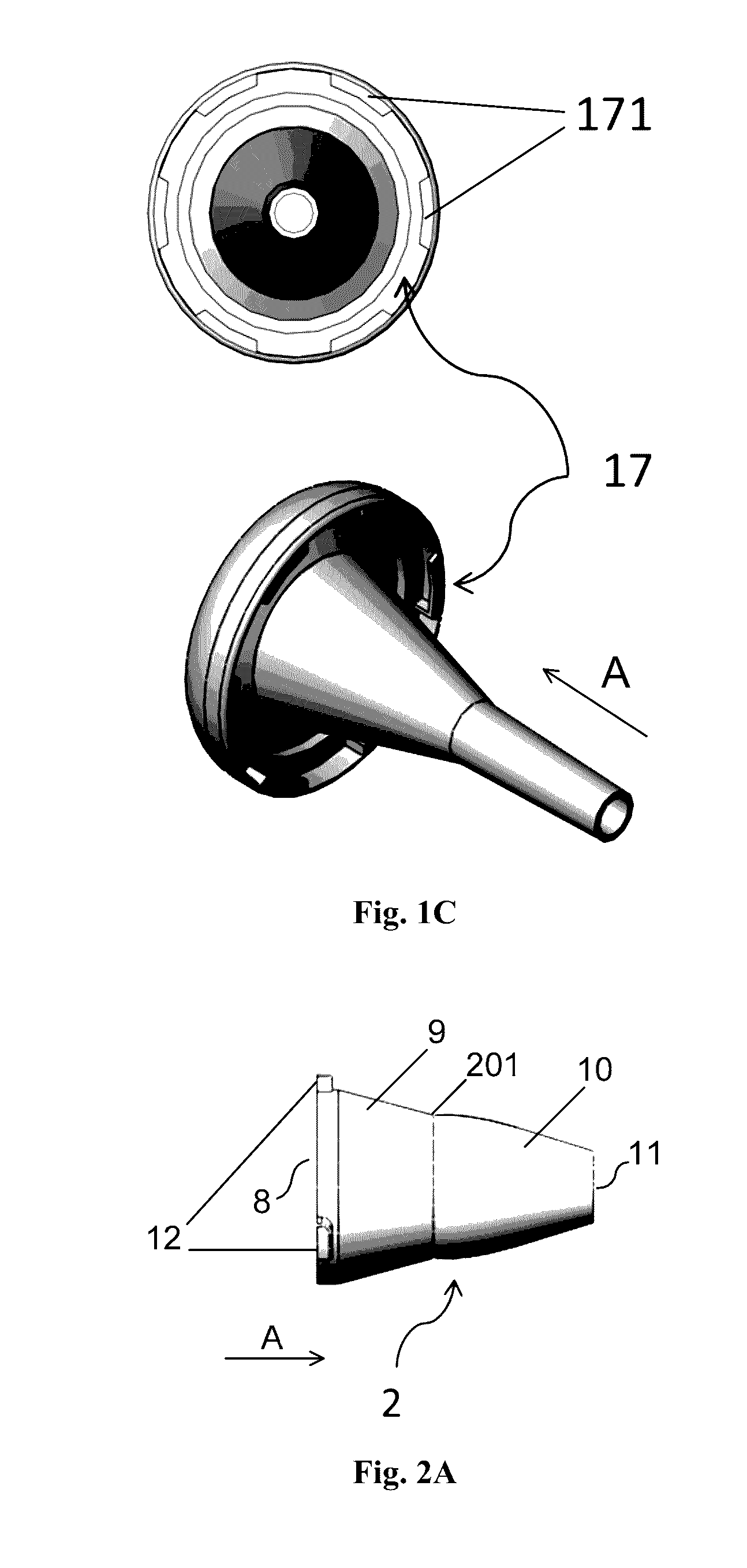
[0030]In one embodiment, the device for loading an implant into a delivery system, according to the present invention, includes a guide cap, a guider and a guiding tube, which are described below in greater detail with reference to the accompanying drawings.

[0031]FIGS. 1A, 1B and 1C are schematic illustrations of a guide cap in...


PUM

PropertyMeasurementUnit
Diameteraaaaaaaaaa

Abstract

A device and method for loading an implant into a delivery system are disclose which are capable of simplifying operations required in interventional surgery using the implant. The device includes a guide cap (1), a guider (2) and a guiding tube (3). The guide cap (1) has a conical section (101) and a straight or conical tube (103) in communication with a small open end (102) of the conical section, and the conical section has a large open end (104) that flares outward, thereby forming a flange (105) facing the tube (103). The guider (2) has tapered sections (9, 10) that are tapered along an axis of the guider and thus form large and small open ends (8, 11). The small open end (11) has a diameter greater than a diameter of the small open end (102) of the conical section of the guide cap (1). The guide cap (1) and the guider (2) are so sized that the flange (105) can cover and be locked to the guider (2), with an end portion of the straight or conical tube (103) protruding from the small open end (11) of the guider (2). The guiding tube (3) is a round tube with two open ends, in which the first open end has a diameter greater than the diameter of the small open end (102) of the conical section of the guide cap and smaller than the diameter of the small open end (11) of the guider.

Description

TECHNICAL FIELD[0001]This invention relates to device and method for loading an implant into a delivery system.BACKGROUND[0002]Heart valve diseases are some of the most commonly diagnosed cardiac diseases in China, and some of them are found to be heart valve damage caused by rheumatic fever. In recent years, the continually aging population has driven an increasing incidence of valvular degeneration (including calcification, mucoid degeneration, etc.) and valvular damage caused by metabolic disorders in China[0003]Minimally invasive interventional surgery offers a variety of advantages, including needlessness of sternotomy, minimal patient trauma and quick recovery. In the recent ten years, the development shows that not only the diseases curable by traditional medical and surgical treatments but also some diseases that the traditional approaches could not handle can be treated by the interventional therapies. After entering the twenty-first century, researches on interventional th...

Claims


Application Information

Patent Timeline
IPC IPC(8): A61F2/95B65B5/04A61F2/24
CPCA61F2/95B65B5/04A61F2/2436A61F2/2418A61F2/2427A61F2/9522A61F2002/9528Y10T29/53909Y10T29/53917Y10T29/53987A61F2230/0067A61F2/9525A61F2/962
Inventor LIU, XIANGWU, MINGMINGLI, YUHE, ZHIXIUGUI, BAOZHUWANG, HAISHANCHEN, GUOMINGCHEN, SHAOHUILUO, QIYI
Owner SHANGHAI MICROPORT CARDIOFLOW MEDTECH CO LTD
Why Eureka
Try Eureka