Rate and Place of Stimulation Matched to Instantaneous Frequency

a technology of instantaneous frequency and stimulation rate, applied in the field of hearing implant systems, can solve the problems of limited current amplitude, phase duration cannot be arbitrarily short, and fewer electrode channels are available for coding

Active Publication Date: 2016-09-29
MED EL ELEKTROMEDIZINISCHE GERAETE GMBH
View PDF2 Cites 6 Cited by
  • Summary
  • Abstract
  • Description
  • Claims
  • Application Information

AI Technical Summary

Problems solved by technology

The phase duration cannot be arbitrarily short because, the shorter the pulses, the higher the current amplitudes have to be to elicit action potentials in neurons, and current amplitudes are limited for various practical reasons.
Thus, fewer electrode channels are available for coding important temporal and spectral properties of the sound signal such as speech onset.
But some stimulation arrangements are quite power consuming, especially when neighboring electrodes are used as current sinks.
Such systems are known to have various limitations including:A possible change of perceived frequency as a function of stimulation current level for a given stimulation location and rate is not taken into account (see FIG. 7 which shows frequency percepts elicited at different intracochlear stimulation locations by different stimulation rates delivered at different stimulation current levels).The available range of perceived frequencies coded by different stimulation rates is restricted to the band pass limits of the assigned filters (see FIG. 8 which shows non-overlapping frequency ranges perceived by stimulating three adjacent electrode locations at band-specific stimulation rates).A change in instantaneous frequency of an input frequency component is only partly translated into a change of stimulation location (Instantaneous stimulation rates within the analyzed frequency range stay at the location of the electrode, see FIG. 8).Multiple frequency components within one band pass filter cannot be assigned a specific stimulation location and rate.
This individual location-frequency map is used to either position an electrode within the cochlea so as to match the electrode location to the individual location-frequency map, or to map an already inserted electrode so as to provide “stimuli only to the parts of the cochlea that have reduced or no residual hearing.” This approach requires that residual hearing be sufficiently preserved to measure the individual location-frequency map via acoustic ABR, and therefore is not usable for cochlear implant patients without residual acoustic hearing.
But, the described method does not take into account individual rate-pitch saturation functions and uses a 1:1 mapping of the acoustic component frequencies to the electrical pulse rates.

Method used


Image

  • Rate and Place of Stimulation Matched to Instantaneous Frequency
  • Rate and Place of Stimulation Matched to Instantaneous Frequency
  • Rate and Place of Stimulation Matched to Instantaneous Frequency

Examples


Embodiment Construction

[0050]Embodiments of the present invention enable an optimal integration of all the different kinds of electrical stimulation cues needed for robust frequency perception: stimulation location, stimulation rate, and stimulation level. In general terms, the stimulation rates are primarily driven by relevant frequency components, especially for low frequencies.

[0051]FIG. 9 shows an example of a frequency percept of 320 Hz elicited by a stimulation rate of 320 pps at a matched stimulation location. Furthermore, a change of an input frequency is translated into a change of stimulation rate and location. FIG. 10 shows how different stimulation rates elicit corresponding frequency percepts when stimulated at individually matched stimulation locations. Because the frequency percept for a fixed stimulation rate and location generally changes as a function of stimulation level, individually mapped functions of stimulation rate and location to perceived frequency will depend on the stimulation...


PUM


Abstract

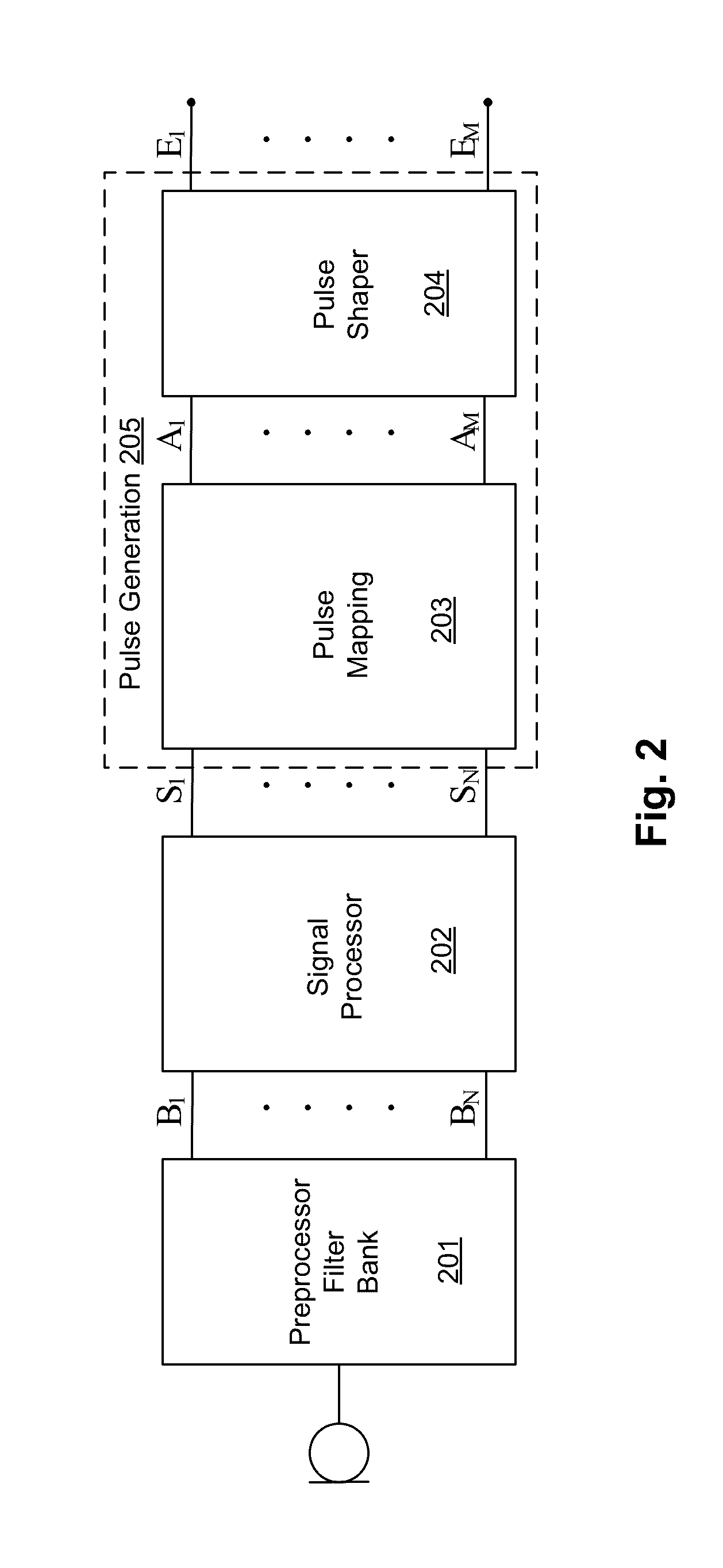
A signal processing arrangement generates electrical stimulation signals to stimulation contacts in an implanted cochlear implant array. An input sound signal is decomposed into dominant psychophysically relevant frequency components, with each frequency component changing over time in frequency and level. Each frequency component is coded as a patient-specific, frequency-specific function of stimulation location, rate, and level to produce a sequence of requested stimulation events having an instantaneous frequency and level. And the electrical stimulation signals are generated from the requested stimulation events for delivery by the stimulation contacts to adjacent auditory neural tissue.

Description

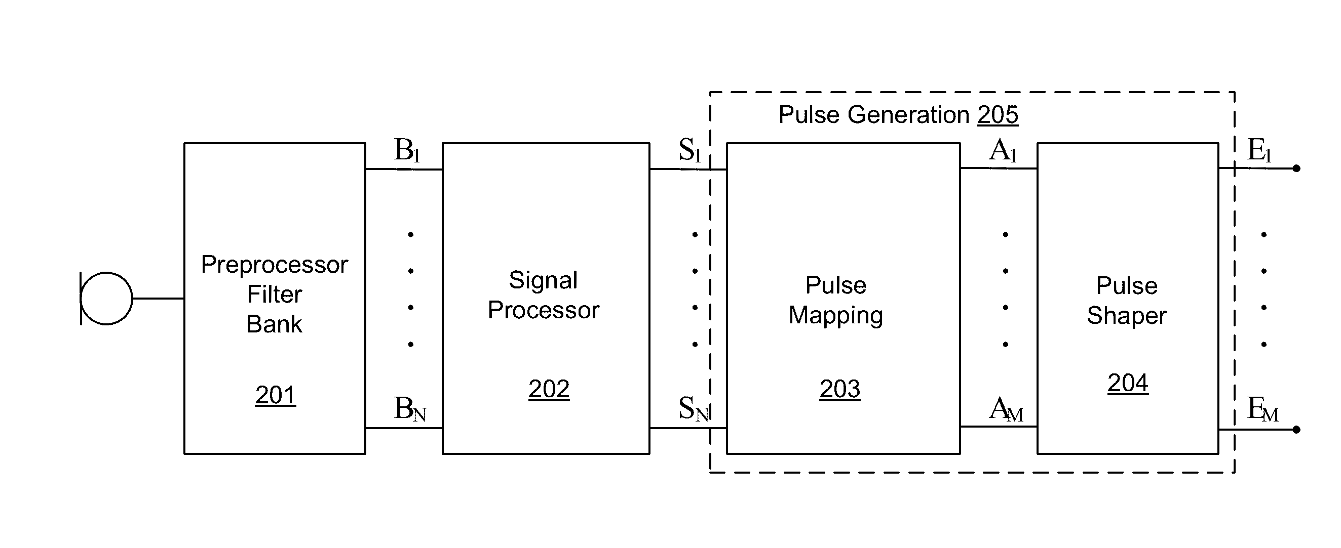
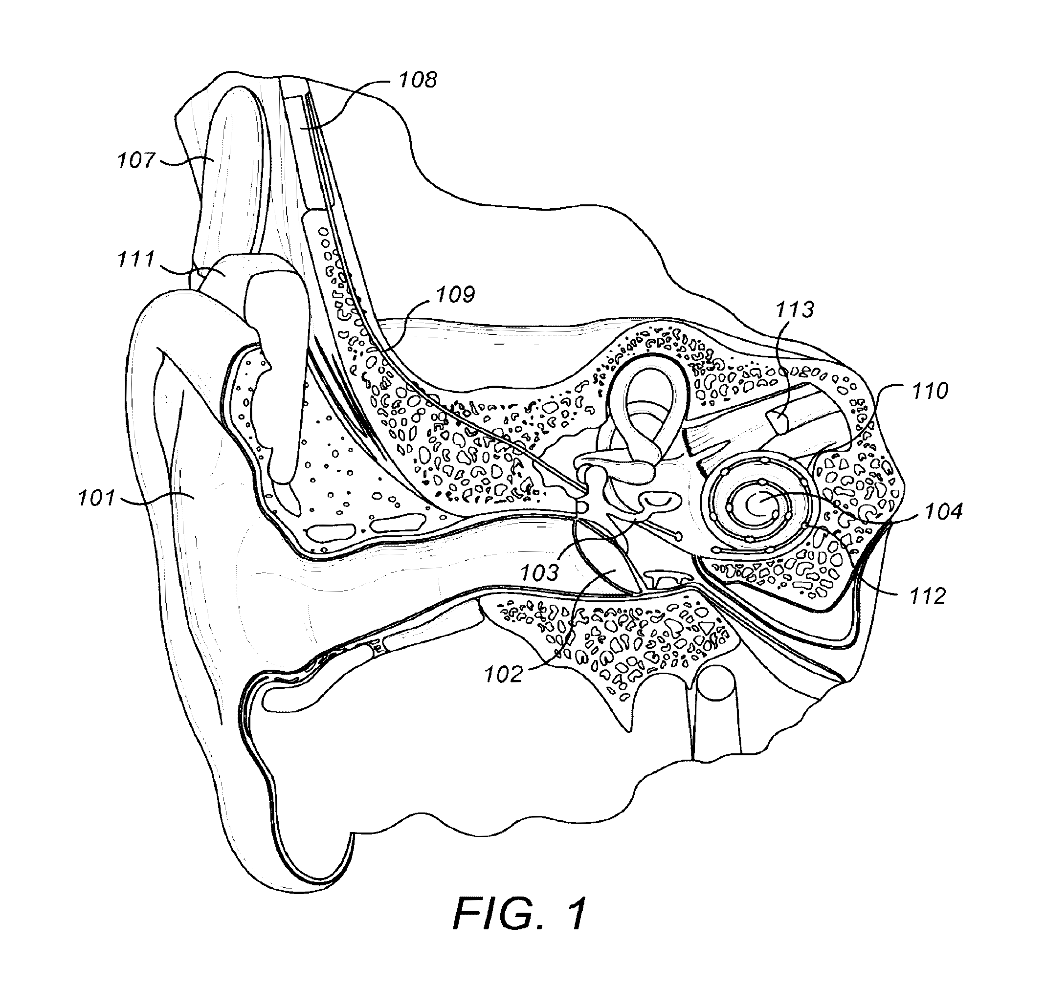
[0001]This application claims priority from German Patent Application DE 102015104614, filed Mar. 26, 2015, from U.S. Provisional Patent Application 62 / 212,643, filed Sep. 1, 2015, and from U.S. Provisional Patent Application 62 / 212,642, filed Sep. 1, 2015, all of which are incorporated herein by reference in their entireties.FIELD OF THE INVENTION[0002]The present invention relates to hearing implant systems, and more specifically, to techniques for producing electrical stimulation signals in such systems.BACKGROUND ART[0003]A normal ear transmits sounds as shown in FIG. 1 through the outer ear 101 to the tympanic membrane 102, which moves the bones of the middle ear 103 (malleus, incus, and stapes) that vibrate the oval window and round window openings of the cochlea 104. The cochlea 104 is a long narrow duct wound spirally about its axis for approximately two and a half turns. It includes an upper channel known as the scala vestibuli and a lower channel known as the scala tympani...

Claims


Application Information

Patent Timeline
Patent Type & Authority Applications(United States)
IPC IPC(8): A61N1/36A61N1/05
CPCA61N1/0541A61N1/36032A61N1/36038A61N1/36039A61N1/025H04R25/48H04R25/502H04R25/70
Inventor SCHLEICH, PETERSCHATZER, REINHOLD
Owner MED EL ELEKTROMEDIZINISCHE GERAETE GMBH
Why Eureka
Try Eureka