Component and method for fabricating a component

a technology of components and manufacturing methods, applied in the direction of burner details, machines/engines, continuous combustion chambers, etc., can solve the problems of limited ability to take advantage of 3d printing capabilities to cool high temperature materials, limited material 3d printing is currently limited, etc., and achieves the effect of high temperature resistance surfa

Inactive Publication Date: 2016-09-29
GENERAL ELECTRIC CO
View PDF7 Cites 19 Cited by
  • Summary
  • Abstract
  • Description
  • Claims
  • Application Information

AI Technical Summary

Benefits of technology

[0007]In another exemplary embodiment, a method for fabricating a component including the steps of providing a metallic powder to a base material, the metallic powder being of a dissimilar material to the base material, heating the metallic powder to a temperature sufficient to weld at least a portion of the metallic powder to form an initial layer, sequentially forming additional layers over the initial layer by heating a distributed layer of the metallic powder to a temperature sufficient to weld at least a portion of the distributed layer of the metallic powder and weld the formed additional layers to underlying layers, repeating the steps of sequentially forming the additional layers over a previously formed layer to form a formed portion of the component, and optionally removing the formed p

Problems solved by technology

However, 3D printing is currently limited to materials which are considered to be easily weldable.
However, the high temperature materials are typically not considered to be weldable using 3D printing techniques.
Therefore, the ability to take advantage of 3D printing capabilities to cool high temperature m

Method used


Image

  • Component and method for fabricating a component
  • Component and method for fabricating a component
  • Component and method for fabricating a component

Examples


Embodiment Construction

[0014]Provided are a component having a high temperature resistant surface and a method for fabricating a component having a high temperature resistant surface. Embodiments of the present disclosure, in comparison to components and methods not using one or more of the features disclosed herein, provide additive manufacturing components including high temperature materials, increase temperature resistance, decrease fabrication costs, decrease material waste, increase fabrication efficiency, provide attachment of 3D manufactured portions to high temperature resistant materials, or a combination thereof.

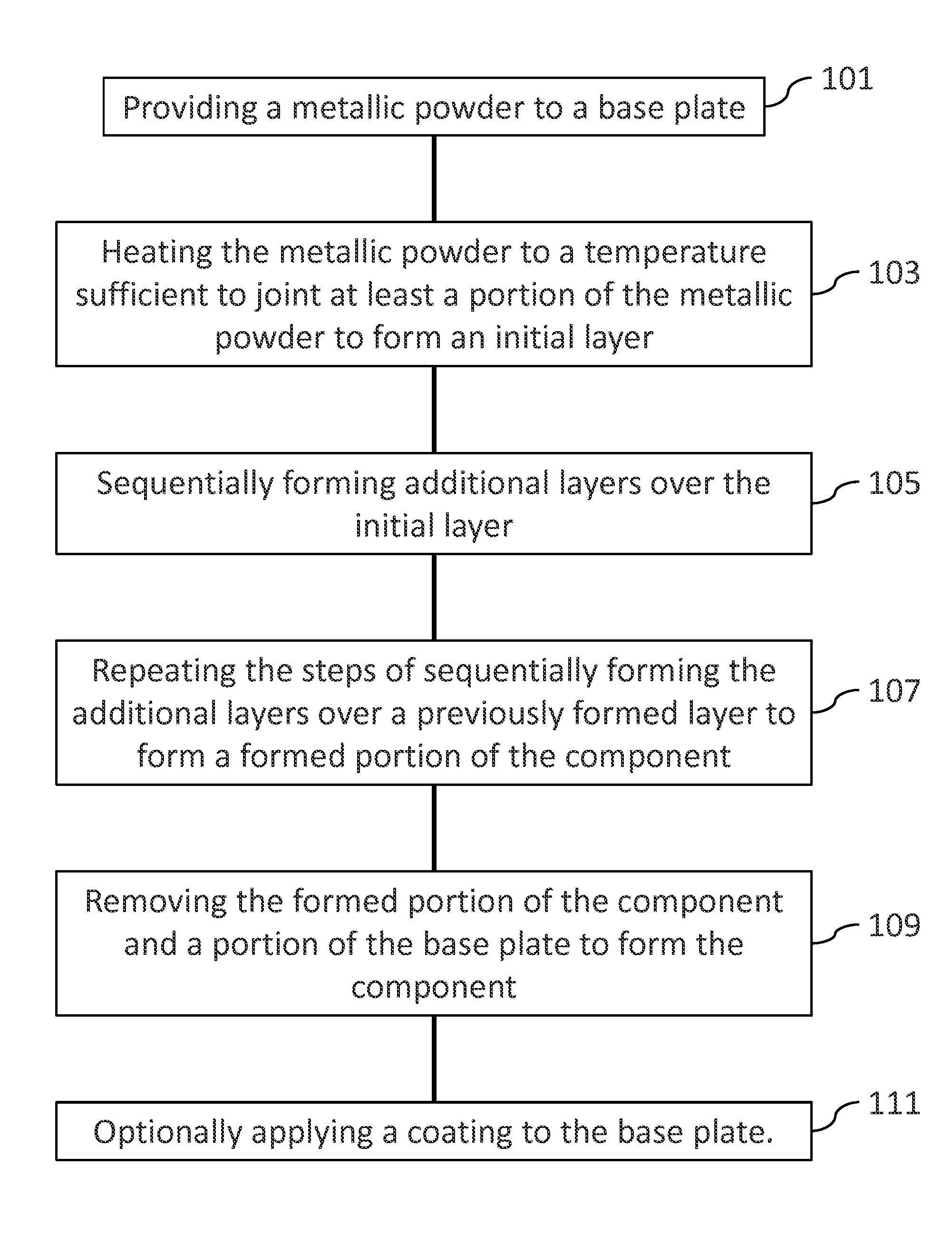
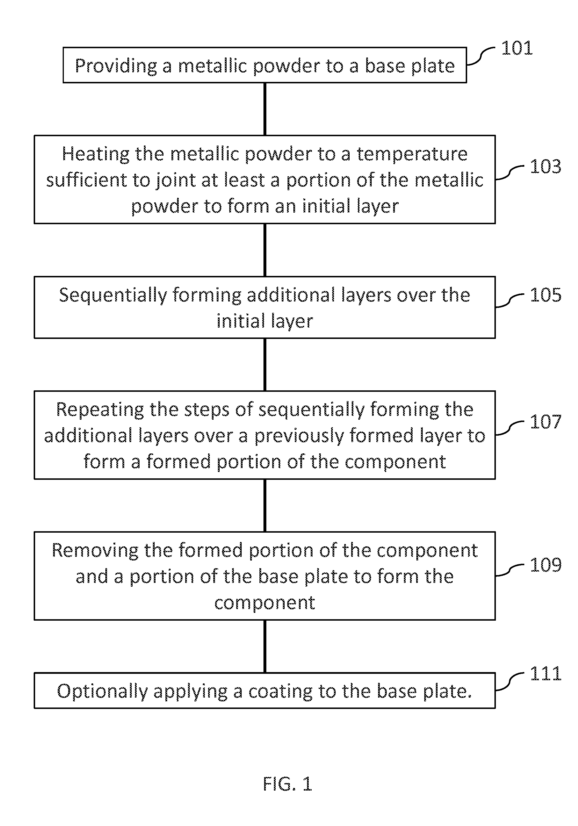
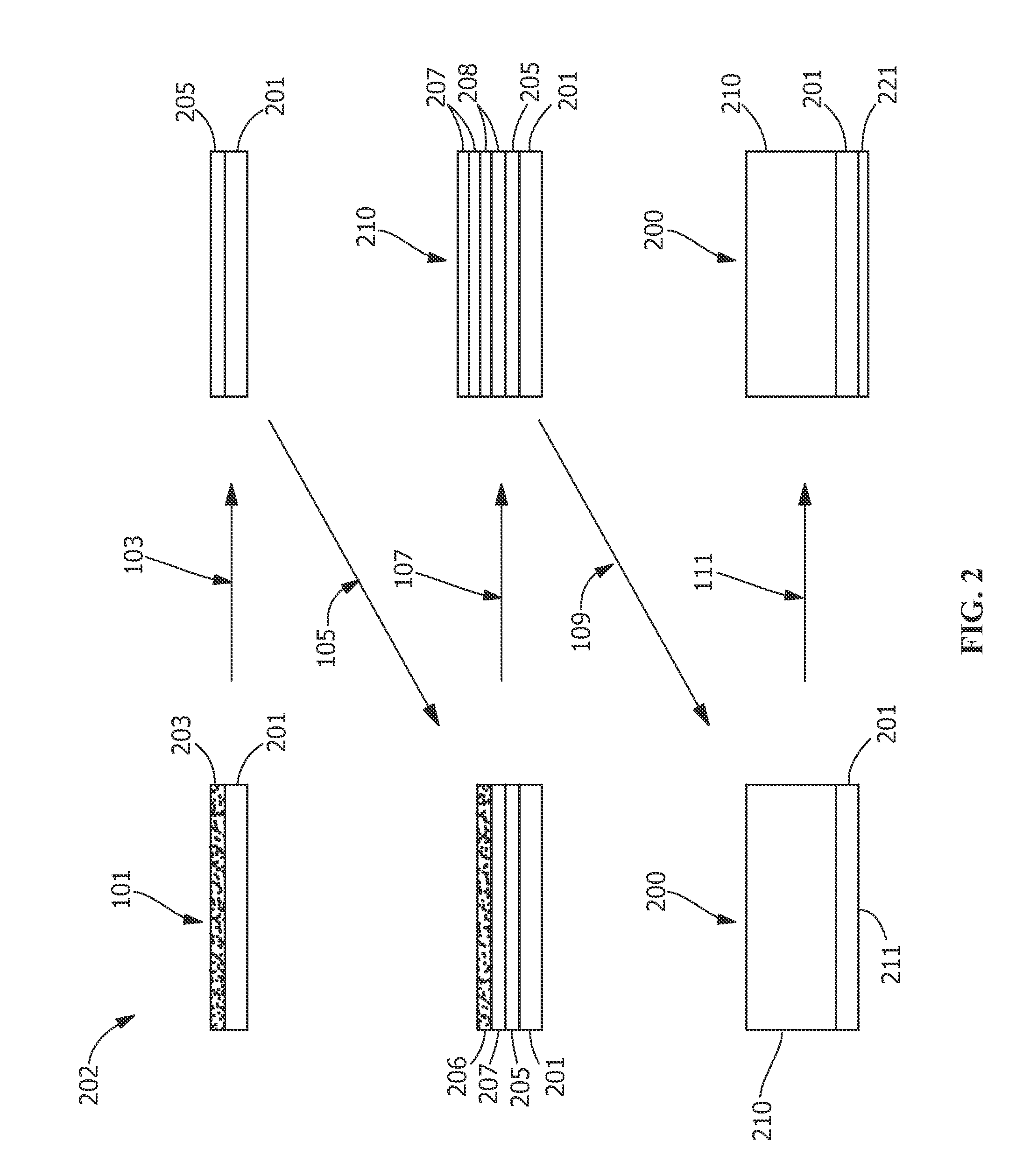
[0015]Referring to FIGS. 1-2, in one embodiment, a method 100 for fabricating a component 200 includes an additive method. Additive methods include any manufacturing method for making and / or forming net or near-net shape structures. As used herein, the phrase “near-net” refers to a structure, such as the component 200, being formed with a geometry and size very similar to the final geom...


PUM

PropertyMeasurementUnit
Temperatureaaaaaaaaaa
Compositionaaaaaaaaaa
Electrical resistanceaaaaaaaaaa

Abstract

Provided is a method for fabricating a component having a high temperature resistant surface. The method includes the steps of providing a metallic powder to a base material, heating the metallic powder to a temperature sufficient to join at least a portion of the metallic powder to form an initial layer, sequentially forming additional layers over the initial layer by heating a distributed layer of the metallic powder to a temperature sufficient to join at least a portion of the distributed layer of the metallic powder and join the formed additional layers to underlying layers, repeating the steps of sequentially forming the additional layers over a previously formed layer to form a formed portion of the component, and optionally removing the formed portion of the component and a portion of the base material. Also provided is a component having a high temperature resistant surface.

Description

FIELD OF THE INVENTION[0001]The present invention is directed toward a component and a method for fabricating a component. More specifically, the present invention is directed to a three-dimensional manufactured component having a high temperature resistant surface.BACKGROUND OF THE INVENTION[0002]Turbine systems are continuously being modified to increase efficiency and decrease cost. For example, modifying the turbine system to operate at increased temperatures can increase the efficiency of the turbine system. One method for increasing the operating temperature of the turbine system includes forming cooling features in the system components. These cooling features are often formed using specific manufacturing methods, such as three-dimensional (3D) printing, which permits the formation of intricate or complex cooling features. However, 3D printing is currently limited to materials which are considered to be easily weldable.[0003]Another method for increasing the operating tempera...

Claims


Application Information

Patent Timeline
IPC IPC(8): B23K15/00B23K26/342B32B15/01B22F3/105C22F1/10B22F3/15B23K26/00B23H7/02
CPCB23K15/0086B23K15/0093B23K26/0006B23K26/342B23H7/02B22F3/1055B33Y80/00B22F3/15B32B15/01B23K2203/08B23K2203/166B23K2203/18B33Y10/00C22F1/10B22F7/08B22F10/00B22F10/36B22F10/66B22F10/25B22F10/28B22F10/64B22F2998/10B22F3/24B22F5/009B22F7/06F01D5/288F23R2900/00018F05D2230/42F05D2300/11F05D2230/30F05D2230/40F05D2300/175B22F2999/00F23R3/002F23D2212/203B23K2103/08B23K2103/18B23K2103/166Y02P10/25B22F2003/247B22F2003/242
Inventor SCHICK, DAVID EDWARDLACY, BENJAMIN PAULMEANS, GREGORY SCOTTLUM, KASSY MOYBARNELL, STEVEN JOHN
Owner GENERAL ELECTRIC CO
Why Eureka
Try Eureka