Hydrogen precooling system

Inactive Publication Date: 2016-09-29
HITACHI PLANT MECHANICS
View PDF1 Cites 6 Cited by
  • Summary
  • Abstract
  • Description
  • Claims
  • Application Information

AI Technical Summary

Benefits of technology

[0025]According to the hydrogen precooling system of the invention, in a hydrogen precooling system in a hydrogen filling facility for filling a tank with hydrogen gas reserved at high pressure by pressure differential expansion by way of an opposite side valve, in a process of expanding and compressing, by expanders, more specifically, for example, by hydrogen turbine, reciprocating mechanical expander, rotary expander, and scroll type expander, or a combination of them, the hydrogen gas is lowered in temperature, and the hydrogen gas is precooled by making use of this cold heat energy, it is possible to present a precooling system used for lowering the temperature of the hydrogen gas at the final filling spot of the hydrogen system, simple in construction, small in burden of maintenance and management tasks, lowered in running cost including the power consumption cost, and lowered in the temperature of hydrogen gas.

Problems solved by technology

On the other hand, in the currently developed fuel cell vehicle, the maximum temperature limit in hydrogen filling is about 85° C., due to temperature limits by material of the fuel tank, and operating temperature limits of the fuel cell main body.
Moreover, owing to the properties of the hydrogen, when filled with hydrogen gas directly without installing any means, the temperature at the time of filling with hydrogen exceeds maximum temperature upper limit of 85° C., which leads to various problems such as temperature limits due to material of the fuel tank, operation temperature limits of the fuel main body cell, and lowering of pressure due to cooling after filling, and hence various methods have been proposed and realized, such as heat exchanger or other cooling means disposed in a route for filling with hydrogen gas, and filling a hydrogen vehicle with hydrogen gas while cooling by this cooling means (see, for example, Patent Document 1).

Method used


Image

  • Hydrogen precooling system
  • Hydrogen precooling system
  • Hydrogen precooling system

Examples


Embodiment Construction

[0030]An embodiment of the hydrogen precooling system of the present invention is described below by reference to the accompanying drawings.

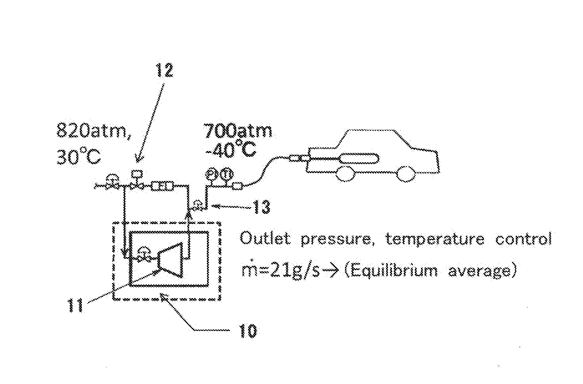
[0031]This hydrogen precooling system is a precooling system used for lowering the temperature of hydrogen gas at a final filling unit of the hydrogen station, that is, in a hydrogen precooling system installed in a hydrogen filling facility for filling a tank with hydrogen gas reserved at a high pressure by pressure differential expansion by way of an opposite side valve, the temperature of the hydrogen gas is lowered by an expander in a process of expanding and compressing the hydrogen gas, and the hydrogen gas is precooled by lowering the temperature of hydrogen gas by an expansion machine in a process of expanding and decompressing, and the hydrogen gas is precooled by making use of its cold heat energy.

[0032]More specifically, as in a final expansion mechanism of hydrogen gas of a hydrogen station shown in FIG. 3, a partial gas of hydrogen ...


PUM


Abstract

[Purpose]
[Problem] To present a precooling system for lowering the temperature of hydrogen gas at a final filling unit of a hydrogen of a hydrogen station simple in construction, small in the load of maintenance and management tasks, and capable of lowering the running cost including the cost of consumption power source.
[Solving Means] To precool hydrogen gas by lowering the temperature of hydrogen gas by an expander 11 in a process of expanding and compressing the hydrogen gas, and by making use of its cold heat energy.

Description

TECHNICAL FIELD[0001]The present invention relates to a hydrogen system, especially, to an attachment system of a hydrogen filling facility for filling a fuel tank of a hydrogen vehicle such as a fuel cell automobile (hereinafter called hydrogen vehicle) with a hydrogen gas as a fuel, from a hydrogen gas supply source, more particularly to a precooling system used for lowering the temperature of the hydrogen gas at a final filling unit of a hydrogen station.BACKGROUND ART[0002]The hydrogen gas used as fuel for a hydrogen vehicle, when expanded adiabatically from high temperature (isenthalpic expansion) in a portion of expansion valve or the like provided in a path for filling with hydrogen gas, is expanded in a region of higher region than its reversing temperature (−58° C.) due to its properties, and is hence characterized to be elevated in temperature before expansion owing to the Joule-Thompson effect.[0003]Therefore, at a hydrogen station, when filling a fuel tank of a hydrogen ...

Claims


Application Information

Patent Timeline
Patent Type & Authority Applications(United States)
IPC IPC(8): F17C5/06
CPCF17C5/06F17C2221/012F17C2223/0123F17C2227/0362F17C2270/0168F17C2270/0184F17C2227/0358F17C2225/0123F17C2223/036F17C2225/036F17C2227/0157F17C2227/0346F17C2227/0355F17C2227/043F17C2260/023F17C2265/065F17C2270/0178Y02E60/32
Inventor YOSHIDA, JUNKANEKO, TAKAYUKI
Owner HITACHI PLANT MECHANICS
Why Eureka
Try Eureka