System and method for iterative condition monitoring and fault diagnosis of electric machines

a technology of condition monitoring and fault diagnosis, applied in the field of motor current signature analysis (mcsa) processes, can solve the problems of large computation complexity requirements of diagnostic signal processing, large complexity and memory occupancy capacity, and the inherent vulnerability of the mcsa diagnosis process to noise and interferen

Active Publication Date: 2016-09-29
THE UNIVERSITY OF AKRON
View PDF8 Cites 46 Cited by
  • Summary
  • Abstract
  • Description
  • Claims
  • Application Information

AI Technical Summary

Benefits of technology

[0009]In light of the foregoing, it is a first aspect of the present invention to provide a method of detecting a fault in an AC (alternating current) electric motor, comprising the steps of monitoring, at a computer system, a motor current signal applied to the AC electric motor; obtaining, at the computer system, a motor current spectrum signature; identifying, at the computer system, n fault characteristic frequency signatures from the motor current spectrum signature, wherein n is an integer value; identifying, at the computer system, m random noise frequency signatures from the motor current spectrum signature, wherein m is an integer value equal to n; comparing, at the computer system, an amplitude of the n fault characteristic frequency signature with an amplitude of the m random noise frequency signature; generating, at the computer system, at least one initial detection matrix including at least one matrix element, such that each the matrix element is associated with the comparison of the n fault characteristic frequency signature amplitude and the m random noise frequency signature amplitude; assigning, at the computer system, a binary 1 to to the matrix element if the amplitude of the n fault characteristic frequency signature is greater than the amplitude of the m random noise frequency signature to identify the presence of a fault, or assigning a binary 0 to the matrix element if the amplitude of the fault characteristic frequency signature is less than the amplitude of the random noise frequency signature amplitude to identify the presence of a non-fault; generating, at the computer system, a probability distribution based on the at least one initial detection matrix; applying, at the computer system, a predetermined probability decision metric threshold to the probability distribution of the at least one initial detection matrix to generate at least one intermediate matrix having at least one binary decision element, wherein the second generating step and the applying step are performed for a predetermined number of iterations; and generating a final binary result at the computer system.

Problems solved by technology

In addition, other time-frequency analysis methods, such as adaptive statistical time-frequency distributions, and Wigner-Ville distributions, have also achieved successful performance; however they require overwhelming complexity and memory occupancy capacity.
In a majority of the abovementioned methods, the operating point limitations of the electric motor, and other electrical machines, as well as the large computation complexity requirements of diagnostic signal processing has been problematic.
However the fundamental limitation of the MCSA diagnosis process is its inherent vulnerability to noise and interference, as MCSA relies on an extremely small fault frequency.
That is, small frequency tone detection in the whole motor current spectrum is easily distorted by interference from harsh industrial noise in the surrounding environment of the electric machine, as well as the low quality of power applied to operate the motor, and the transient operation of the motor.
Furthermore, in modern energy conversion systems, especially in critical service applications that are subject to harsh industrial applications, the low signal-to-noise ratio (SNR) of the motor current signal makes identifying a reliable fault indication a challenging issue.

Method used


Image

  • System and method for iterative condition monitoring and fault diagnosis of electric machines
  • System and method for iterative condition monitoring and fault diagnosis of electric machines
  • System and method for iterative condition monitoring and fault diagnosis of electric machines

Examples


Embodiment Construction

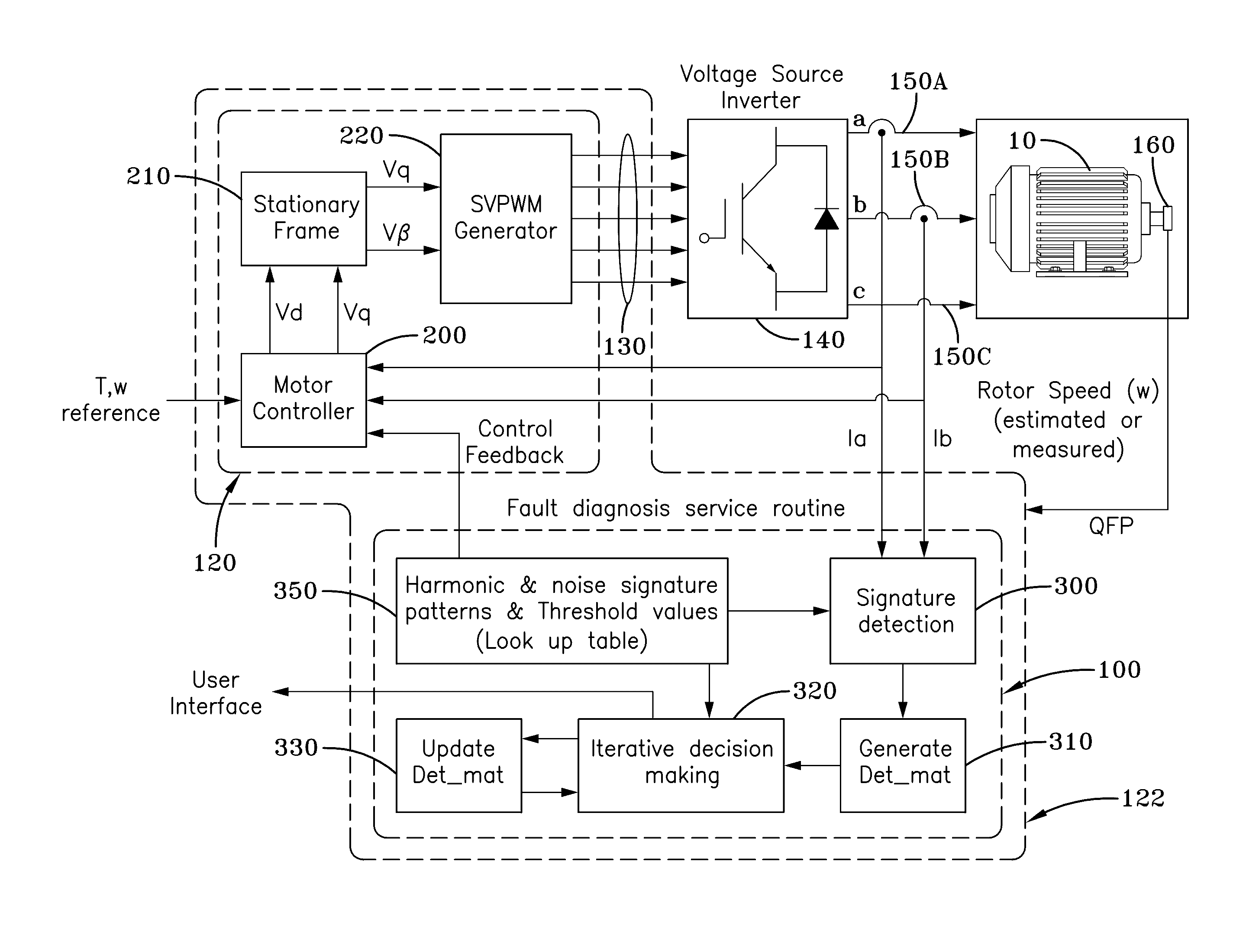
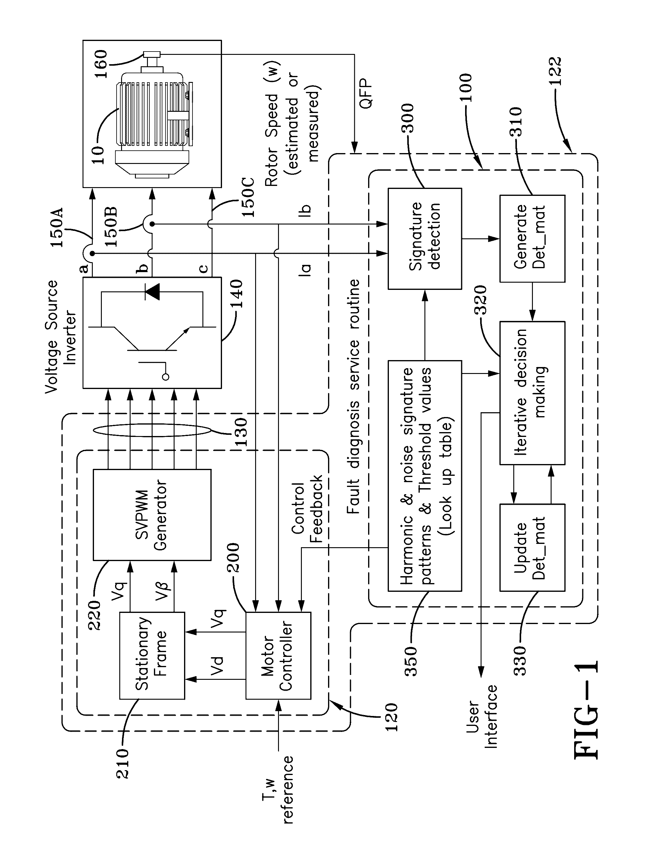
[0031]A system for iterative condition monitoring and fault diagnosis (i.e. condition monitoring system) of an electric machine 10, such as an electric motor or generator, is generally referred to by numeral 100, as shown in FIG. 1 of the drawings. It should be appreciated that the condition monitoring system 100 may be embedded in a digital signal processor (DSP) or any other suitable computing device. The condition monitoring system 100 to be discussed is configured to operate in conjunction with a motor control system 120 that is configured to generate and apply suitable motor control signals 130 to a voltage source inverter 140. The voltage source inverter 140 generates a three-phase power signal that is delivered via electrical lines 150A, 150B, and 150C to power the electric motor 10, so as to rotationally drive a shaft 160 provided thereby. It should be appreciated that the condition monitoring system 100 and motor control system 120 may be provided together or separately as ...


PUM


Abstract

A system and method for iterative condition monitoring and fault diagnosis of an electric machine, such as an electric motor, is configured to iteratively analyze a pattern of multiple fault signatures in a motor current signal under harsh, noisy conditions. As such, the present invention evaluates patterns of multiple fault signatures that are spread over the wide motor current spectrum, by effectively rejecting signal distortions, harsh noise, and interference from the dynamic operation of the electric machine.

Description

CROSS-REFERENCE TO RELATED APPLICATION[0001]This application claims the benefit of U.S. Provisional Application No. 62 / 138,489 filed on Mar. 26, 2015, the content of which is incorporated herein by reference.TECHNICAL FIELD[0002]The present invention generally relates to motor current signature analysis (MCSA) processes used to monitor and diagnose faults of an electric motor. Particularly, the present invention relates to a MCSA process for monitoring and diagnosing faults of electric motors operating in harsh industrial environments where the signal-to-noise ratio of a motor current signal is low. More particularly, the present invention relates to a MCSA process that simultaneously utilizes multiple fault signature patterns, noise signal frequency patterns, and fundamental harmonic current frequency patterns of a motor current signal to reliably identify faults of an electric motor operating in harsh, noisy operating environments.BACKGROUND OF THE INVENTION[0003]Electric motors a...

Claims


Application Information

Patent Timeline
Patent Type & Authority Applications(United States)
IPC IPC(8): G01R31/34G01R29/26
CPCG01R29/26G01R31/34G01R23/20G01R31/343
Inventor CHOI, SEUNGDEOG
Owner THE UNIVERSITY OF AKRON
Why Eureka
Try Eureka