System and method of underground water detection

Active Publication Date: 2016-09-29
UTILIS ISRAEL
View PDF2 Cites 13 Cited by
  • Summary
  • Abstract
  • Description
  • Claims
  • Application Information

AI Technical Summary

Benefits of technology

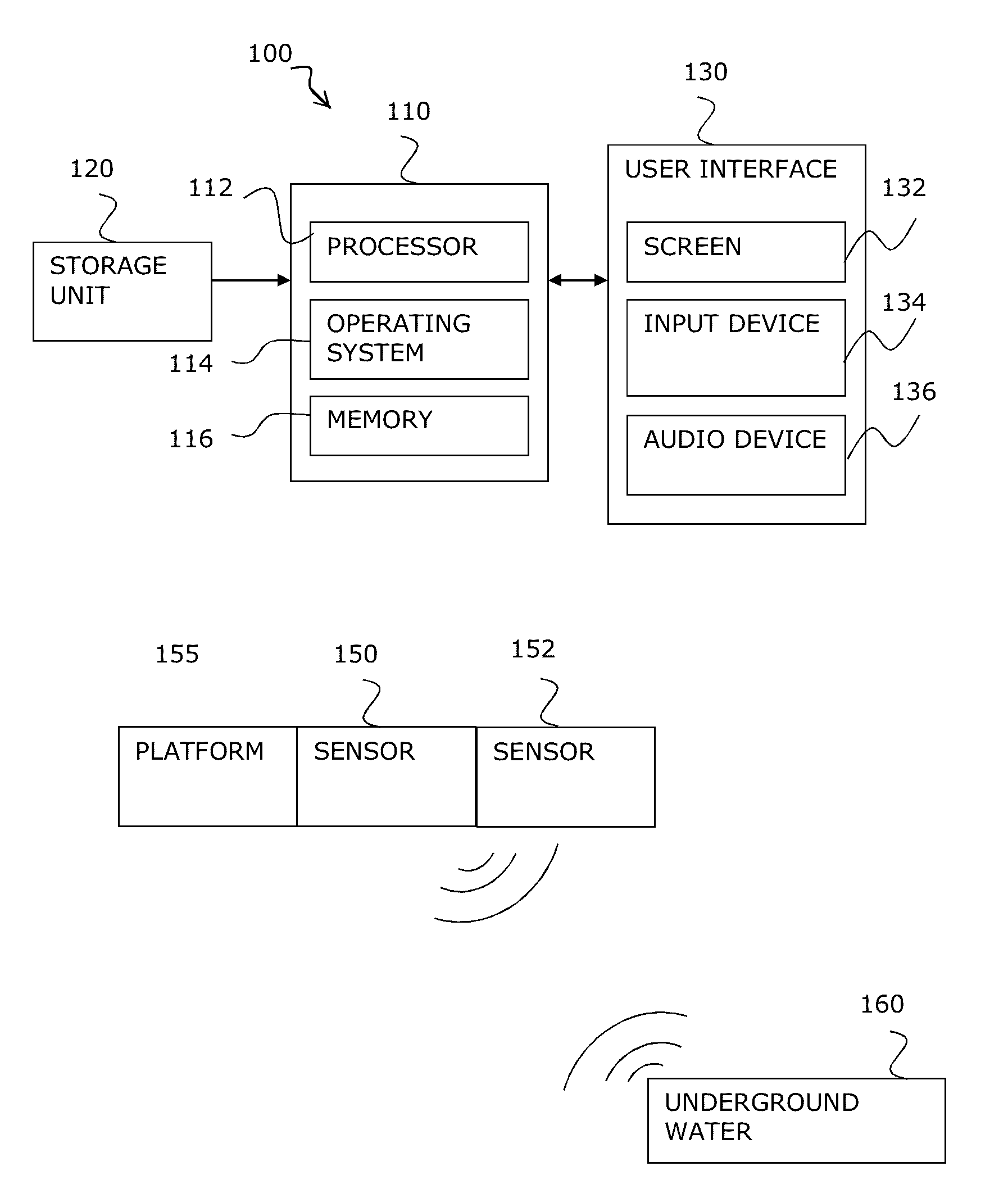
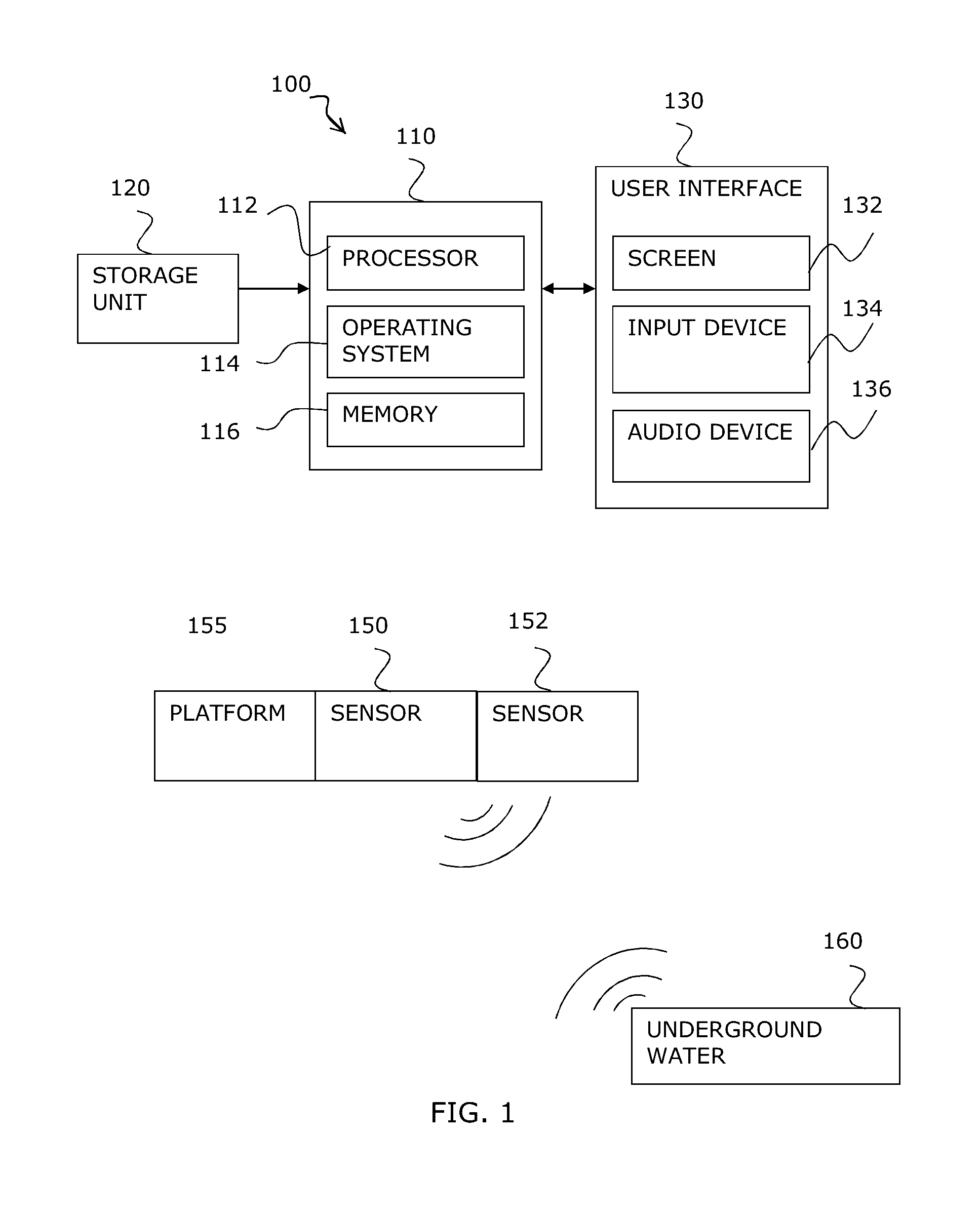
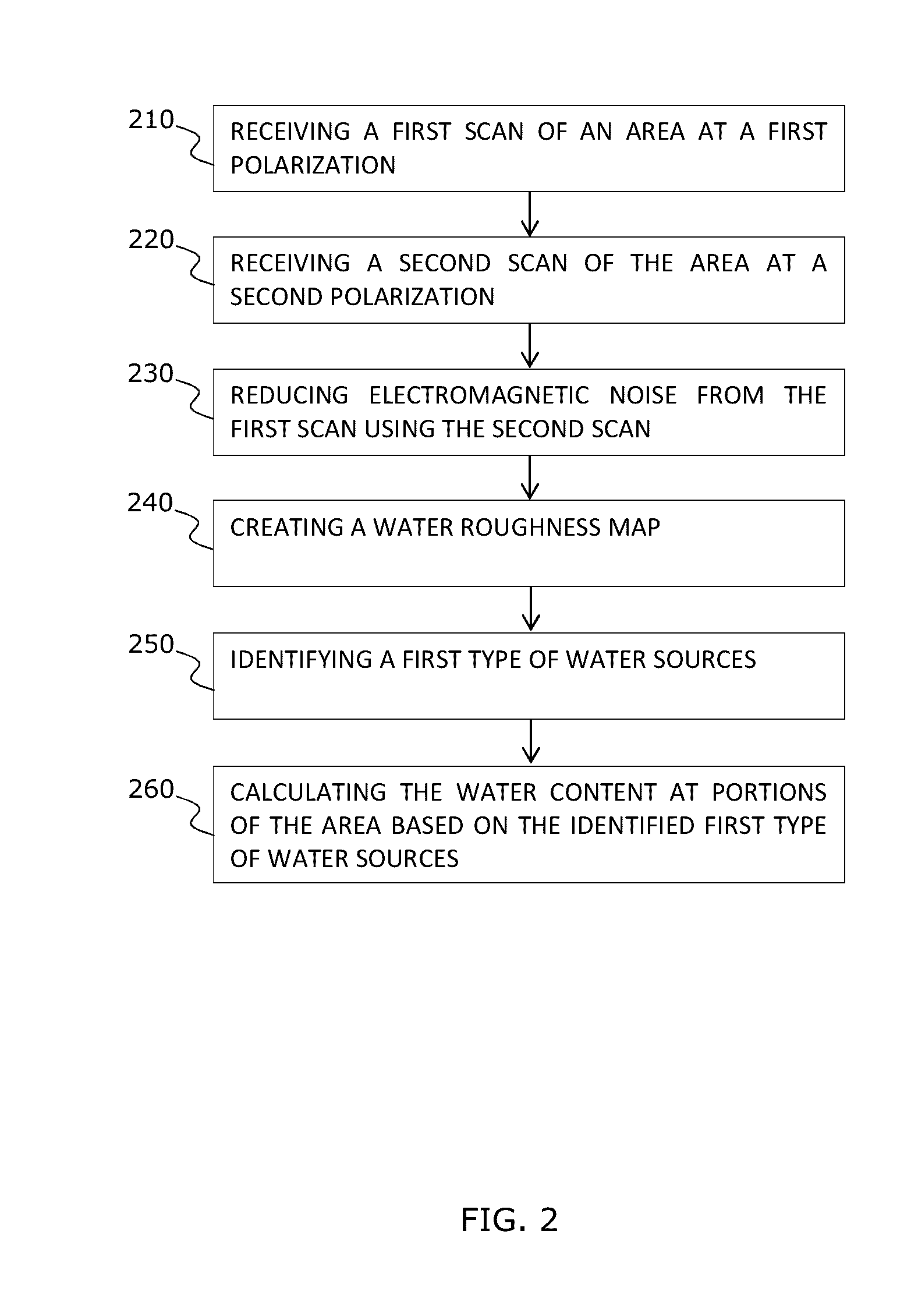
[0005]Embodiments of the invention are directed to a system and a method of determining underground liquid (e.g., water) content. Embodiments may include: receiving a first scan of an area at a first polarization, the first scan including first L band microwave reflections from the area, receiving a second scan of the area at a second polarization, the second scan including second L band microwave reflections from the area, the first and second scans being from a first sensor for detecting L band microwave radiation reflections attached to an object located at least 50 meters (“m”), 70 m, 100 m or more, above the area and filtering electromagnetic noise from the first scan using the second scan. Embodiments of the method may include creating a water roughness map based on typical roughness values of various types of water sources and the filtered first scan, identifying a first type of water sources using the water roughness map and the filtered first scan and calculating the water content at locations in the area based on the identified first type of water sources.
[0006]Embodiments of the invention include a method of determining underground liquid (e.g., water)

Problems solved by technology

Shortage in drinking water supply is an acute global problem.
Some of this shortage is caused by extensive leakage of drinking water from water supply systems.
Water leakage can cause over 20-30% and even over 50% of the losses of drinking water in a typical urban water system.
The older the water system the higher the chance for water leakage.
Most water leakages occur underground and are hard to detect.
Such

Method used


Image

  • System and method of underground water detection
  • System and method of underground water detection
  • System and method of underground water detection

Examples


Embodiment Construction

[0021]In the following detailed description, numerous specific details are set forth in order to provide a thorough understanding of the invention. However, it will be understood by those skilled in the art that the present invention may be practiced without these specific details. In other instances, well-known methods, procedures, and components have not been described in detail so as not to obscure the present invention.

[0022]Although embodiments of the invention are not limited in this regard, discussions utilizing terms such as, for example, “processing,”“computing,”“calculating,”“determining,”“establishing”, “analyzing”, “checking”, or the like, may refer to operation(s) and / or process(es) of a computer, a computing platform, a computing system, or other electronic computing device, that manipulates and / or transforms data represented as physical (e.g., electronic) quantities within the computer's registers and / or memories into other data similarly represented as physical quant...


PUM


Abstract

Embodiments of the invention are directed to a method of determining underground liquid (e.g., water) content. Embodiments of the method may include: receiving a scan of an area at a first polarization, the scan scans including first L band microwave reflections from the area. Embodiments of the invention may include receiving an optical data at a wavelength of 1 millimeter to 10 nanometers. Embodiments of the method may further include filtering electromagnetic noise from the scan using the optical data. Embodiments of the method may further include creating a water roughness map based on typical roughness values of various types of water sources and the filtered scan, identifying a first type of water sources using the water roughness map and the filtered scan and calculating the water content at locations in the area based on the identified first type of water sources.

Description

CROSS REFERENCE TO RELATED APPLICATIONS[0001]This application is a continuation in part of U.S. patent application Ser. No. 14 / 666,648, filed on May 24, 2015 and entitled SYSTEM AND METHOD OF UNDERGROUND WATER DETECTION, which is incorporated in its entirety herein by referenceFIELD OF THE INVENTION[0002]The present invention relates generally to remote detection of underground liquid. More specifically, the present invention relates to systems and methods for remote detection of underground liquid content using microwave radiation.BACKGROUND OF THE INVENTION[0003]Shortage in drinking water supply is an acute global problem. Some of this shortage is caused by extensive leakage of drinking water from water supply systems. Water leakage can cause over 20-30% and even over 50% of the losses of drinking water in a typical urban water system. The older the water system the higher the chance for water leakage. Most water leakages occur underground and are hard to detect. Such underground ...

Claims


Application Information

Patent Timeline
IPC IPC(8): G01S13/88G01V11/00G01V3/12
CPCG01S13/885G01V11/00G01V3/12G01S7/411G01V8/005G01V9/02G01S13/90G01S13/867G01S7/025G01S13/9076Y02A90/30G01S13/9027
Inventor GUY, LAURENNEVO, ERAN
Owner UTILIS ISRAEL
Why Eureka
Try Eureka