Optical iq modulator control
a technology of optical iq modulator and control field, applied in the direction of digital transmission, transmission path sub-channel allocation, instruments, etc., can solve the problems of low noise monitor signal, implementation but has some severe disadvantages with respect to single sideband modulation
- Summary
- Abstract
- Description
- Claims
- Application Information
AI Technical Summary
Benefits of technology
Problems solved by technology
Method used
Image
Examples
second embodiment
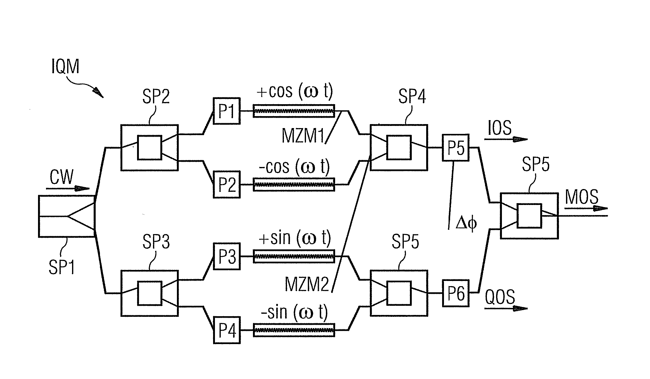
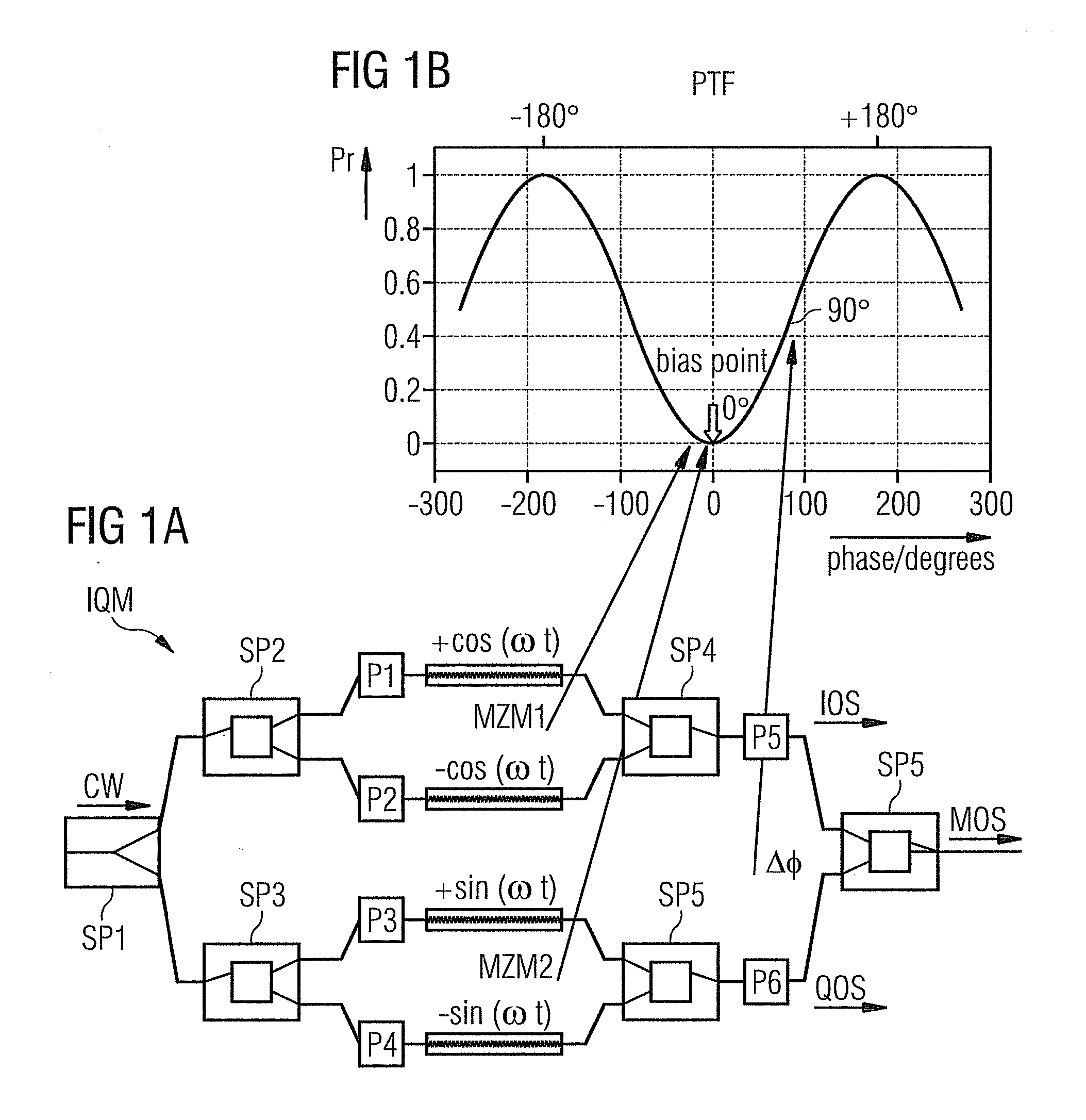
[0083]The second embodiment depicted in FIG. 4 uses a different kind of optical pilot signals PM1, PM2. These pilot signals are generated by electrical pilot modulation signals SM1, SM2 with a basic modulation frequency fco carrying different additional AF (audio frequency) carrier modulation signals M1, M2 with “carrier modulation frequencies” f1 and f2 (e.g. again f1=1.41 kHz, f2=1 kHz). The (electrical) modulation signals may even have identical basic modulation frequencies fco and generate therefore the pilot signals PM1 and PM2 with an optical first basic frequency fcw+fco and an optical second basic frequency fcw fco also additional modulated by f1 and f2 respectively. ASK modulation or, with higher expenditure, each kind of “pilot signal modulation” may be used for the pilot signals. In FIG. 6 are only the relative basis frequency positions fco and +fco of these modulated pilot signals indicated to avoid a confusing number of signals.
[0084]Corresponding to the embodiment of F...
first embodiment
[0086]Hence, the standardized combined modulation signals MI and MQ (neglecting the amplitudes) for the first embodiment according FIG. 3 are
MI(t)=sin(2πf1*t)+cos(2πf2*t)+sin(2πf3*t)=S1+S2_90+S3;
MQ(t)=cos(2πf1*t)+sin(2πf2*t)+sin(2πf4*t)=S1_90+S2+S4.
[0087]The standardized combined modulation signals MI and MQ for the second embodiment using modulated pilot signals PM1, PM2 according FIG. 4 depend on the modulation format (neglecting the amplitudes) e.g. for ASK modulation with carrier modulation signals
M1=sin(2πf1*t) and M2=sin(2πf2*t):
MI(t)=sin(2πfc*t)*sin(2πf1*t)+cos(2πfc*t)*sin(2πf2*t)+sin(2πf3*t)=SM1+SM2_90+S3;
MQ(t)=cos(2πfc*t)*sin(2πf1*t)+sin(2πfc*t)*sin(2πf2*t)+sin(2πf4*t)=SM1_90+SM2+S4;
[0088]Power control signals CS3, CS4 (shown before adjustment as dashed lines in FIGS. 5 and 7) are derived from the further pilot signals PS3, PS4 and the phase shifters P1, P2 and P3, P4 are controlled by associated PTF bias (control) signals bias_I and bias_Q respectively till the output powe...
PUM
 Abstract
Description
Claims
Application Information
 - R&D
- Intellectual Property
- Life Sciences
- Materials
- Tech Scout
- Unparalleled Data Quality
- Higher Quality Content
- 60% Fewer Hallucinations
Browse by: Latest US Patents, China's latest patents, Technical Efficacy Thesaurus, Application Domain, Technology Topic, Popular Technical Reports.
© 2025 PatSnap. All rights reserved.Legal|Privacy policy|Modern Slavery Act Transparency Statement|Sitemap|About US| Contact US: help@patsnap.com


