Power generation system
a power generation system and power generation technology, applied in the direction of engines, mechanical equipment, machines/engines, etc., can solve the problems of insufficient responsiveness of the applied voltage relative to the temperature detection, different responsiveness to the temperature change, etc., to achieve high responsiveness, energy can be extracted efficiently, and power generation efficiency is increased
- Summary
- Abstract
- Description
- Claims
- Application Information
AI Technical Summary
Benefits of technology
Problems solved by technology
Method used
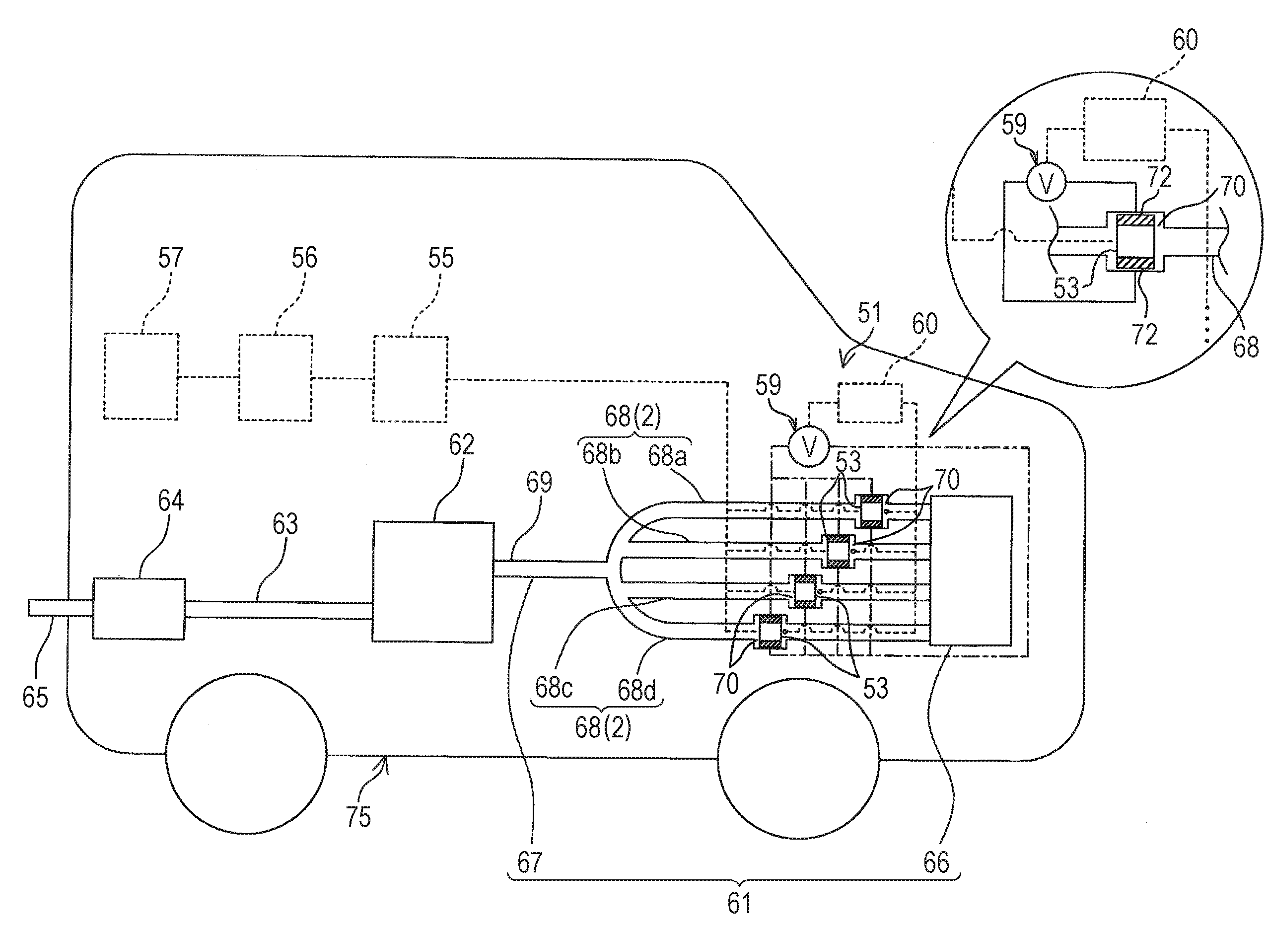
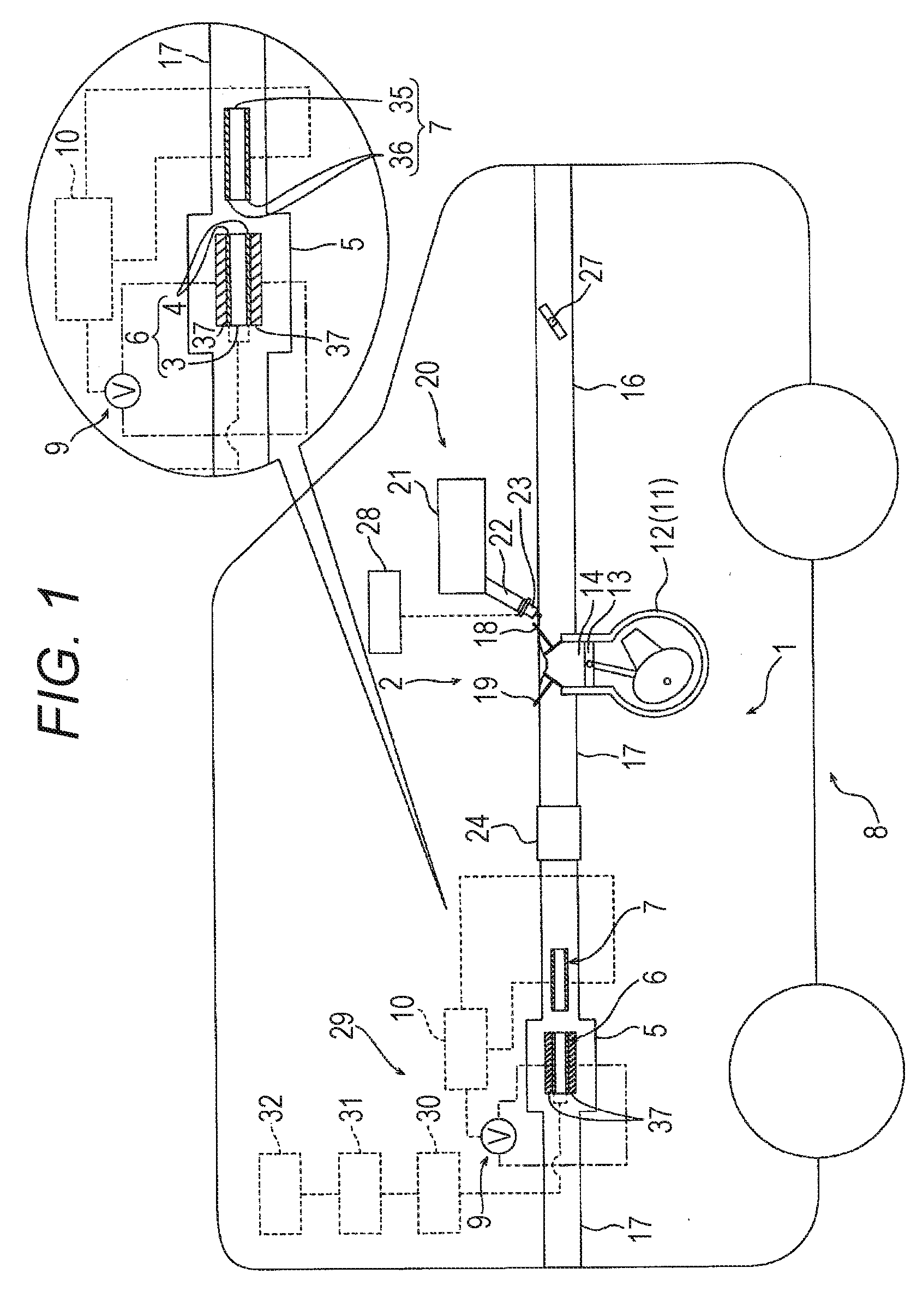
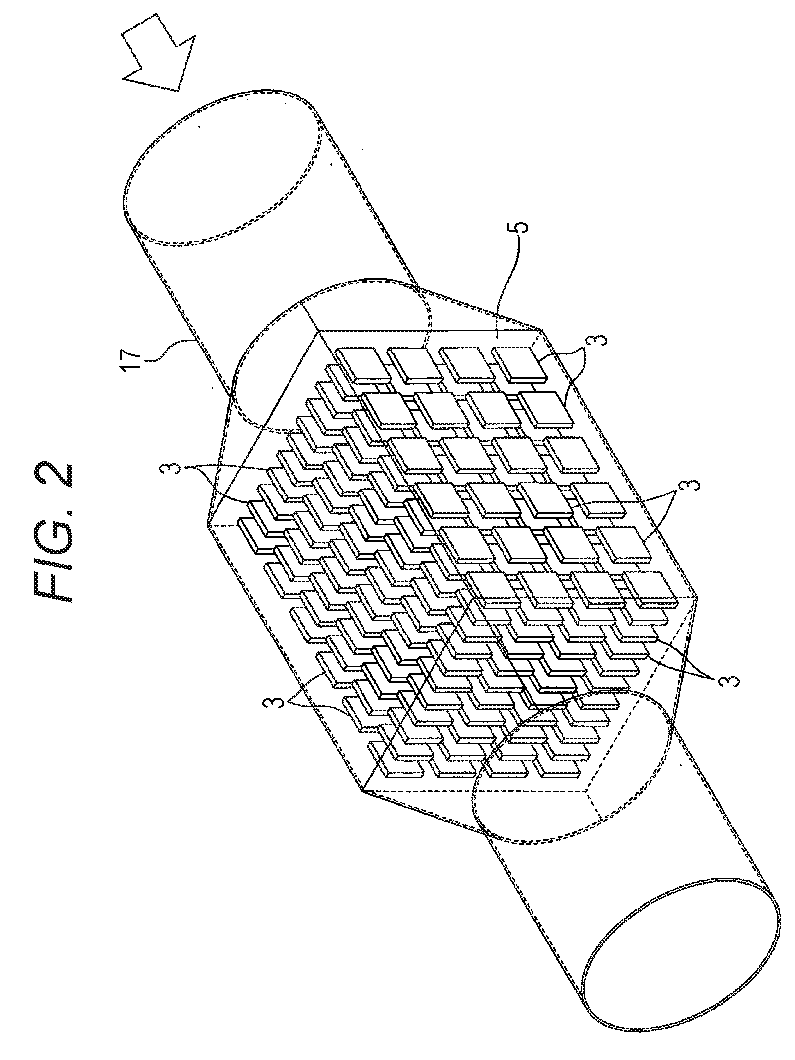
Image

Examples
reference example 1
[0289]A bulk type piezo element (the first device with a silver electrode (second device) formed on each of front and rear surfaces, structure: PZT, Curie point (Tc): 295° C., relative dielectric constant: 2130, Product No.: C-6, FUJI CERAMICS CORPORATION) was cut into a sheet-like shape with a vertical length of 8 mm, a horizontal length of 13 mm, and a thickness of 0.5 mm.
[0290]Next, a 100-kΩ resistor was disposed in parallel to the piezo element. The resistor was provided to monitor the voltage continuously and calculate the generated electric power of the element based on the voltage value.
[0291]A heat gun was used as the heat source. The heat gun and the piezo element were disposed so that the injection port was set 3 cm apart from the piezo element.
[0292]Next, the thermocouple (temperature sensor) was disposed to detect the temperature of each sample. In order to apply voltage, the sample was held between the electrodes of the voltage application device (product number: MODEL ...
PUM
 Abstract
Description
Claims
Application Information