Radar device

a technology of a radar and a ring, which is applied in the direction of measurement devices, using reradiation, instruments, etc., can solve the problems of degrading the performance of following a fast moving target, and the difficulty of arranging the array elements at spacings smaller than the size of the array elemen

Active Publication Date: 2016-09-29
PANASONIC HLDG CORP
View PDF0 Cites 49 Cited by
  • Summary
  • Abstract
  • Description
  • Claims
  • Application Information

AI Technical Summary

Benefits of technology

[0012]One non-limiting and exemplary embodiment of the present disclosure provides a radar device that can prevent generation of an unnecessary grating lobe and achieve a desired directivity pattern even when arranged in the subarray antenna configuration.

Problems solved by technology

With this configuration, the scanning needs to be performed a large number of times to obtain a high resolution, which leads to a degradation in the performance of following a fast moving target.
As for the element spacing of the array antenna, it is difficult to arrange the array elements at spacings smaller than the size of the array element.
However, the dimension of the array element having a subarray antenna configuration is large, and accordingly a large spacing is needed between subarray antennas, which may generate a grating lobe on a directivity pattern of the array antenna.

Method used


Image

  • Radar device
  • Radar device
  • Radar device

Examples


Embodiment Construction

[Underlying Knowledge Forming Basis of the Present Disclosure]

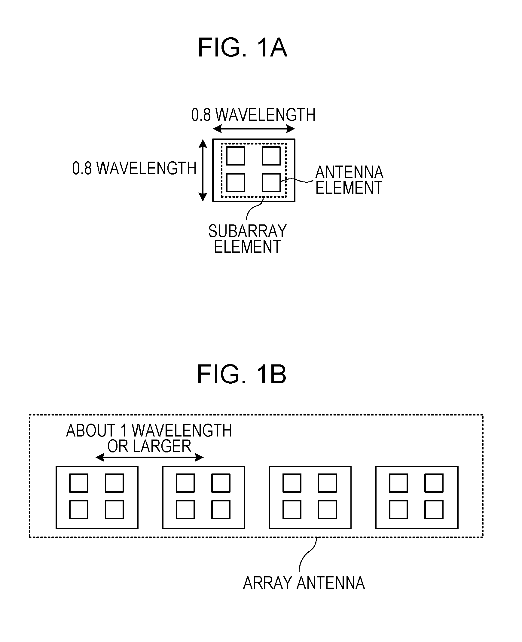
[0034]FIG. 1A illustrates an exemplary subarray configuration (hereinafter, also referred to as a subarray element) including an antenna element. The subarray element illustrated in FIG. 1A includes four antenna elements in a 2×2 matrix. In the example illustrated in FIG. 1A, the subarray element has a dimension of 0.8 wavelength in both the horizontal and vertical directions.

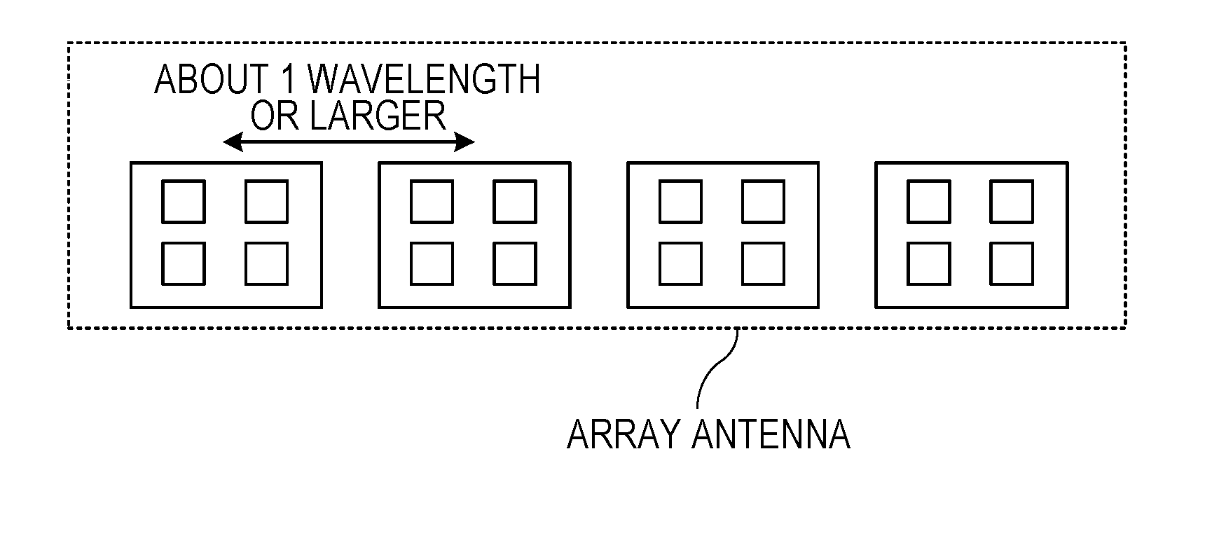
[0035]FIG. 1B illustrates an exemplary array antenna including a linear arrangement of the four subarray elements illustrated in FIG. 1A. Since each subarray element has a dimension of 0.8 wavelength (refer to FIG. 1A) as illustrated in FIG. 1B, a spacing between the subarray elements needs to be about 1 wavelength or larger.

[0036]For example, an array element spacing (predetermined element spacing) for preventing generation of a grating lobe in a range of ±90° of a main lobe is 0.5 wavelength. In the array antenna illustrated in FIG. 1B, the subarra...


PUM


Abstract

A radar transmitter transmits a radar signal through a transmitting array antenna at a predetermined transmission period, and a radar receiver receives a reflected wave signal which is the radar signal reflected by a target through a receiving array antenna. A transmitting array antenna and a receiving array antenna each include multiple subarray elements, the subarray elements in the transmitting array antenna and the receiving array antenna are linearly arranged in a first direction, each subarray element includes multiple antenna elements, the subarray element has a dimension larger than a predetermined antenna element spacing in the first direction, and an absolute value of a difference between a subarray element spacing of the transmitting array antenna and a subarray element spacing of the receiving array antenna is equal to the predetermined antenna element spacing.

Description

BACKGROUND[0001]1. Technical Field[0002]The present disclosure relates to a radar device.[0003]2. Description of the Related Art[0004]Recent studies have been made on a radar device using a radar transmission signal of a short wavelength including microwave or milliwave with which a high resolution is achieved. Development is required on a radar device (wide-angle radar device) that detects objects (targets) including a pedestrian as well as a vehicle in a wide-angle range in order to improve outdoor safety.[0005]A known example of such a radar device is a pulse radar device that repeatedly emits pulsed waves. A wide-angle pulse radar that detects a vehicle and a pedestrian in a wide-angle range receives a mixture of multiple reflected waves from a target (for example, a vehicle) at a short distance and a target (for example, a pedestrian) at a long distance. This requires (1) a radar transmitter to have a configuration to transmit pulsed waves or pulse-modulated waves having a auto...

Claims


Application Information

Patent Timeline
Patent Type & Authority Applications(United States)
IPC IPC(8): H01Q21/08G01S13/931
CPCH01Q21/08G01S7/032G01S7/282G01S7/285G01S13/42G01S7/023G01S13/22G01S13/26G01S13/284G01S13/325G01S13/931G01S7/0234G01S13/4463G01S7/352H01Q21/22G01S2013/0245
Inventor KISHIGAMI, TAKAAKIYOSOKU, NAOYA
Owner PANASONIC HLDG CORP
Why Eureka
Try Eureka