Three Dimensional Depth Mapping Using Dynamic Structured Light

a structured light and depth mapping technology, applied in the field of three-dimensional depth mapping using structured light, can solve the problems of high implementation cost, difficulty in providing ideal beam geometry, and inability to accurately combine motion tracking and feature recognition, and achieve the effect of reducing increasing the resolution of the structured light pattern

Active Publication Date: 2016-09-29
META PLATFORMS TECH LLC
View PDF4 Cites 39 Cited by
  • Summary
  • Abstract
  • Description
  • Claims
  • Application Information

AI Technical Summary

Benefits of technology

[0029]In an embodiment, the dynamic control is configurable to apply increased resolution of the structured light pattern to parts of the scene to apply reduced resolution of the structured light pattern to other parts of the scene.

Problems solved by technology

Drawbacks of such visual imaging include a requirement that the three-dimensional area is sufficiently lit up.
Furthermore the only features that can be tracked are features that are recognized in advance, and motion tracking combined with feature recognition may not give accurate results.
Disadvantages are high cost of implementation, difficulties providing the ideal beam geometry, and laser typical effects such as speckle noise and the possible self interference with beam parts reflected from objects.
Furthermore, there is no means of modulating individual stripes, such as with Gray codes.
Specifically, a disadvantage of using a single source emitter such as an edge emitter laser diode is the fact that the light pattern that it produces can be controlled only as a single unit.
This means that the light pattern can be entirely turned on, off or dimmed but cannot be changed dynamically.
Edge-emitters cannot be tested until the end of the production process.
If the edge-emitter does not function properly, whether due to bad contacts or poor material growth quality, the production time and the processing materials have been wasted.
However, despite the above advantages, the VCSEL array is not currently used for structured light scanning systems for a number of reasons.
The multiple points and overlap between them reduce the detection performance in high density areas in the light pattern and restrict the use of various diffractive design techniques that requires a pre-defined Gaussian beam.
Indeed the problem with a standard diffractive design is that the entire VCSEL laser array is used as a single light source.
The problem becomes more severe in dense light patterns, because in these light patterns there is a need to focus the source beam onto a tiny spot in order to separate the features and this is not possible if the light source is an array of lasers.

Method used


Image

  • Three Dimensional Depth Mapping Using Dynamic Structured Light
  • Three Dimensional Depth Mapping Using Dynamic Structured Light
  • Three Dimensional Depth Mapping Using Dynamic Structured Light

Examples


Embodiment Construction

[0069]The present invention, in some embodiments thereof, relates to three-dimensional depth mapping using structured light, and more particularly, but not exclusively, to a system for tracking in order to provide input to a computer.

[0070]The following applications to the same assignee are hereby incorporated by reference as if fully set forth herein, namely U.S. patent application Ser. No. 13 / 497,589, filed Sep. 19, 2010, International Patent Application No. WO2013 / 088442 filed 13 Sep. 2012, U.S. Provisional Patent Application No. 61 / 926,476 filed 13 Jan. 2014, and U.S. Provisional Patent Application No. 62 / 035,442 filed 10 Aug. 2014.

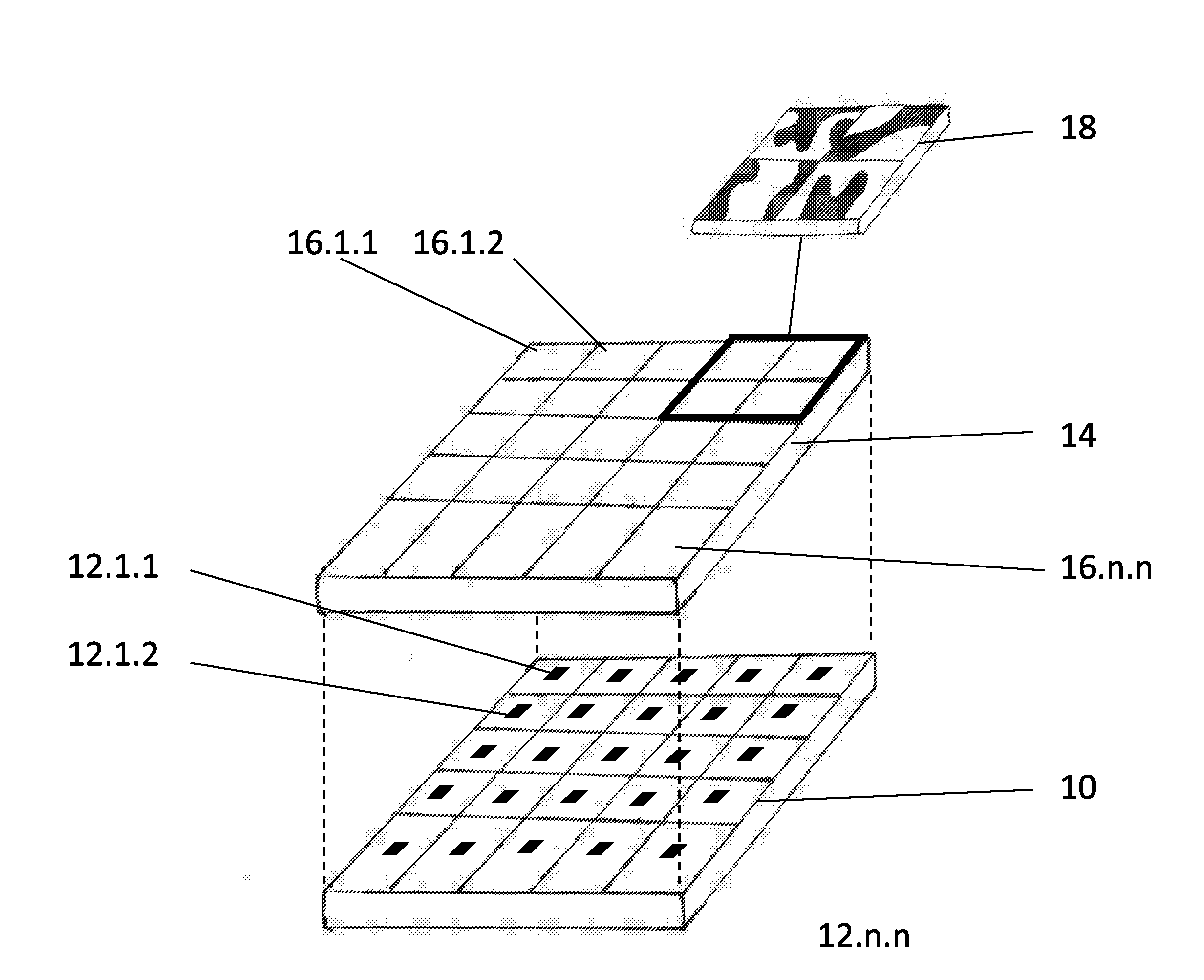
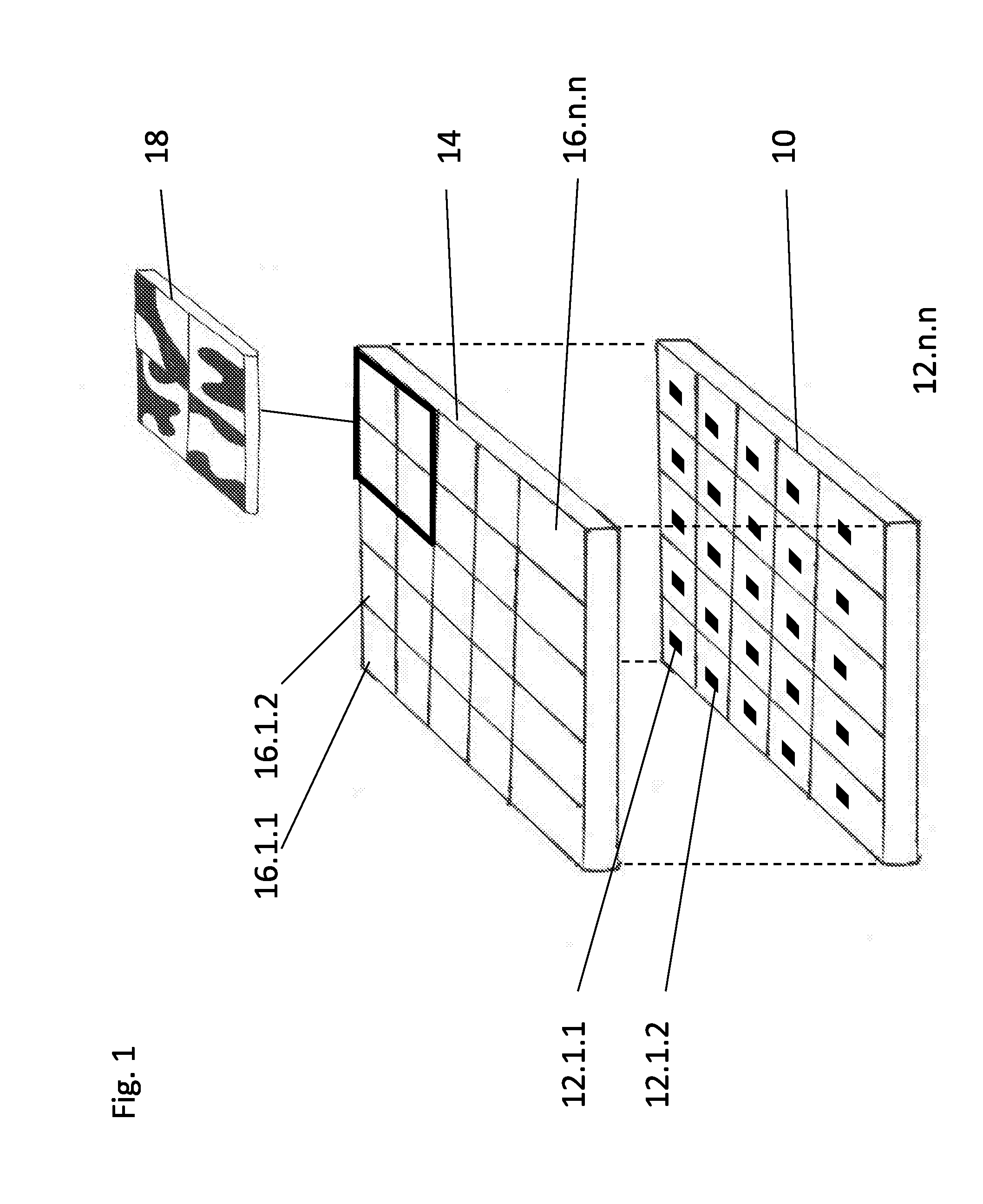
[0071]As discussed above, various devices use structured light patterns to enable gesture recognition and 3D depth mapping. A structured light pattern transmitter includes a light source, for example a laser emitter, and an optical element such as a diffractive optical element (DOE). As many diffractive designs requires a coherent Gaussian shaped beam...


PUM


Abstract

Apparatus for generating a dynamic structured light pattern for optical tracking in three-dimensional space, comprises an array of lasers, such as a VCSEL laser array, to project light in a pattern into a three-dimensional space; and an optical element or elements arranged in cells. The cells are aligned with subsets of the laser array, and each cell individually applies a modulation, in particular an intensity modulation, to light from the laser or lasers of the subset, to provide a distinguishable and separately controllable part of the dynamic structured light pattern. A method of generating a structured light pattern is disclosed, in which light is provided from an array of lasers, and light is individually projected from subsets of the array of lasers to provide differentiated parts of the structured light pattern.

Description

FIELD AND BACKGROUND OF THE INVENTION[0001]The present invention relates to three-dimensional depth mapping using structured light, and more particularly, but not exclusively, to a system for tracking in order to provide input to a computer or like device.[0002]Tracking in order to provide input to a computer, or other computational device, involves such ubiquitous technologies as the computer mouse. Tracking of styluses and fingers in a three-dimensional field in front of the computer is also available and uses various tracking technologies such as visual and IR imaging and ultrasonics. The term ‘tracking’ may refer to following the positioning and motion of an object, and includes processing of inputs received at the tracking computer in order to determine the position or motion. Thus in the case of a computer mouse, tracking may include processing the mouse outputs to determine motion. In the case of an object being followed visually, the term tracking may include image processin...

Claims


Application Information

Patent Timeline
Patent Type & Authority Applications(United States)
IPC IPC(8): H04N13/02H04N13/00G06F3/03G02B27/42G06F3/01G01S17/89
CPCH04N13/0296G02B27/4205G06F3/017G06F3/0304H04N13/0282G02B27/4255H04N13/0022H04N13/0207G06F3/0321G01S7/4815G01S17/46G01S17/89H01S5/423H04N13/128H04N13/207H04N13/282H04N13/296
Inventor ROMANO, NITAYGROSSINGER, NADAVALPERN, YAIRALON, EMIL
Owner META PLATFORMS TECH LLC
Why Eureka
Try Eureka