
Lead identification system

a technology of lead identification and lead, applied in the field of lead identification system, can solve the problem of reducing the inventory of components of the neurostimulation system

Active Publication Date: 2016-10-06
CIRTEC MEDICAL CORP
View PDF1 Cites 6 Cited by
  • Summary
  • Abstract
  • Description
  • Claims
  • Application Information

AI Technical Summary

Benefits of technology

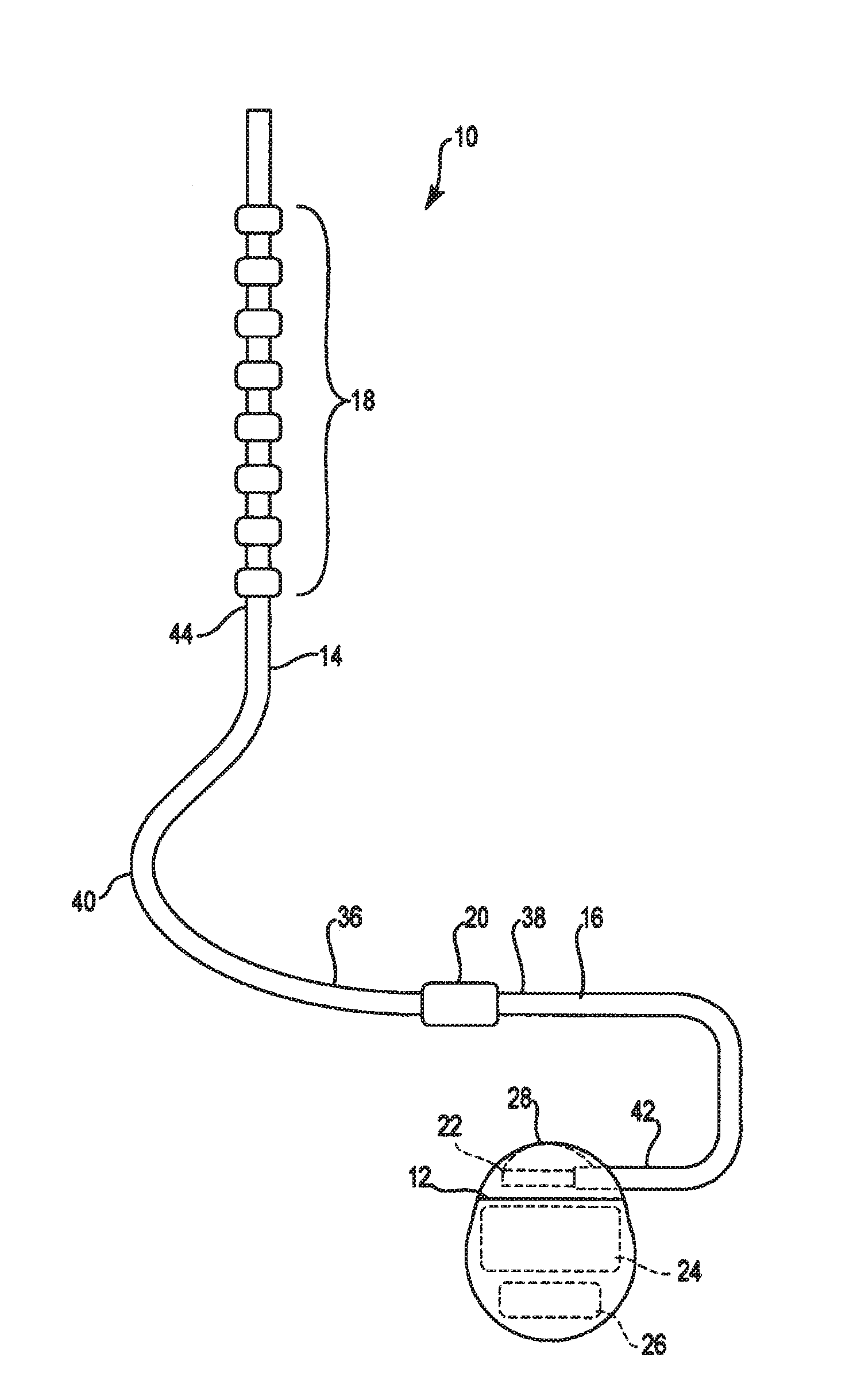
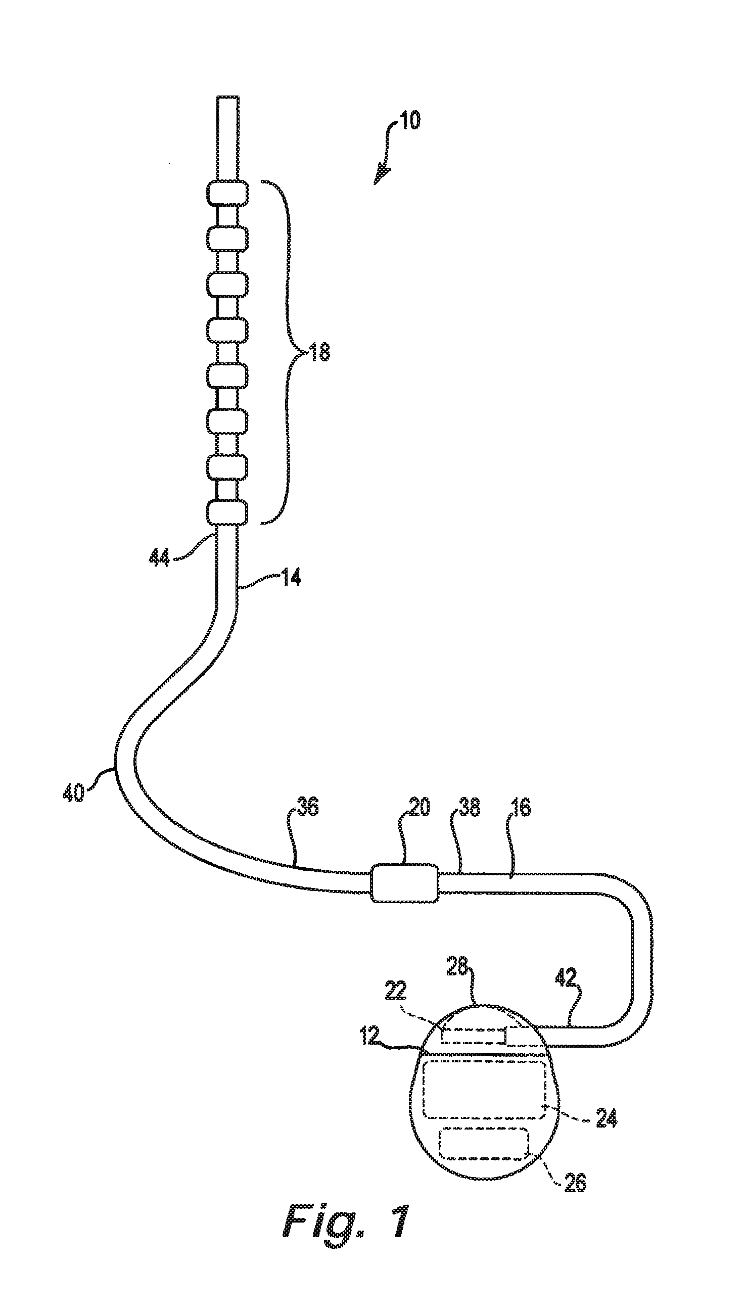
[0010]The present lead identification system provides corresponding lead indicators that permit the surgeon to track the electrodes of a particular therapy delivery element to the correct connectors on an implantable pulse generator. The lead indicators are preferably releasably attachable to the components of the neurostimulation system and can be shifted or reconfigured by the surgeon during the procedure. Consequently, the components of the neurostimulation system, such as the epidural needles, the leads and lead extensions, lead clips, lead anchors, stylets, internal and external pulse generators, and trial cables can all be generic without any labels or indicia. The use of removable lead indicators dramatically reduces the inventory of components for the neurostimulation system.
[0017]The present disclosure is also directed to a lead identification system for tracking a plurality of neurostimulation leads during implantation in a patient. The lead identification system includes a plurality of removable lead indicators each adapted to attach to one of a plurality of epidural needles to identify the leads. One embodiment includes rotating lead indicators attach to each of the epidural needles wherein a rotational orientation of the rotating lead indicators uniquely identify each of the therapy delivery elements. At least one clip adapted to releasably attach to proximal ends of the leads is provided with corresponding lead indicators. The trial cable for conducting trial stimulation includes connectors with corresponding lead indicators. A plurality of removable lead indicator stylets are provided for insertion into lumens at the proximal ends of the leads. A pulse generator is provided with connectors having corresponding lead indicators. The various removable lead indicators permit a surgeon to track electrodes on a particular lead to the corresponding connectors on the pulse generator.

Problems solved by technology

The use of removable lead indicators dramatically reduces the inventory of components for the neurostimulation system.

Method used


Image

  • Lead identification system
  • Lead identification system
  • Lead identification system

Examples


Embodiment Construction

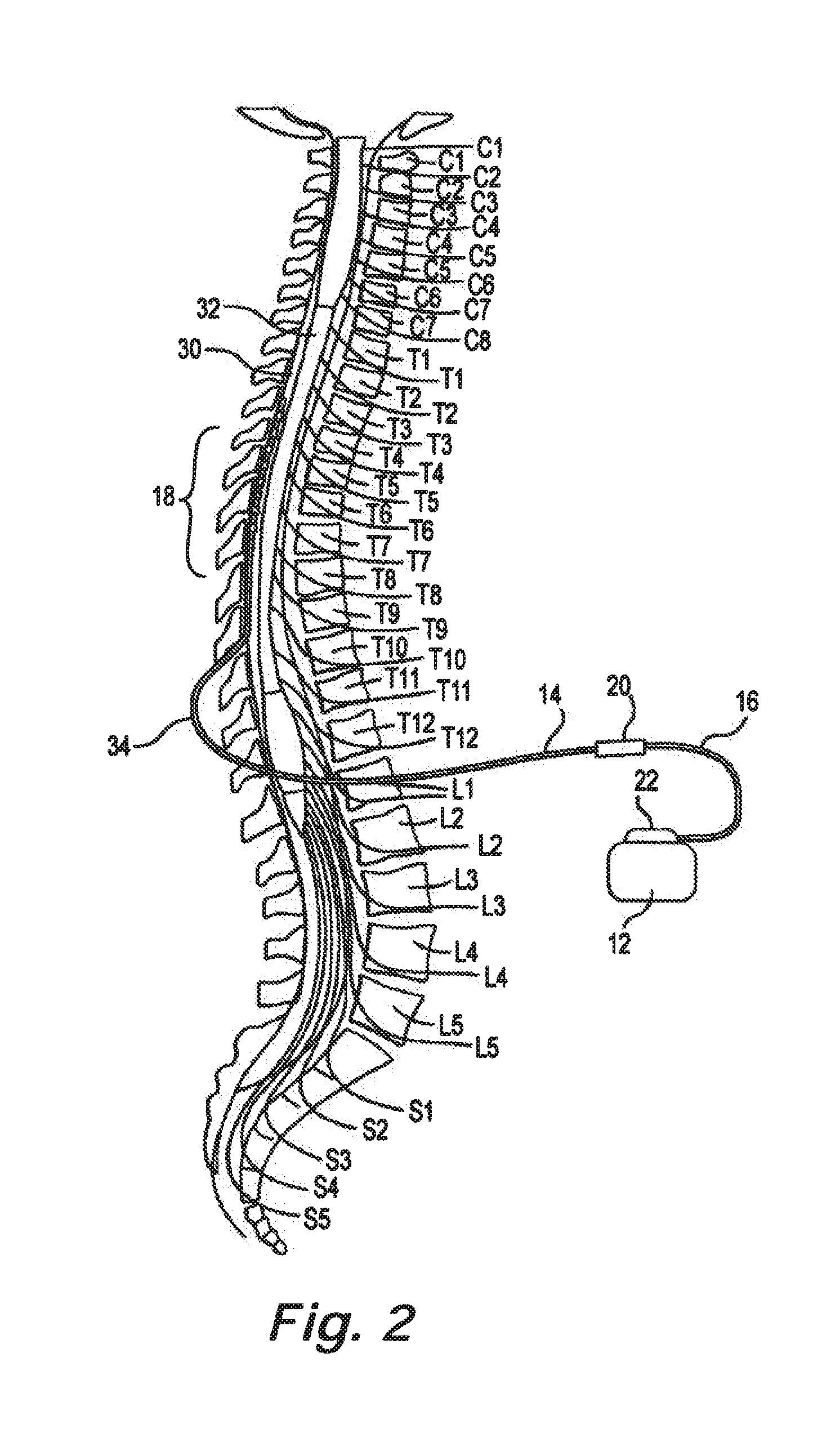
[0036]The description that follows relates to a spinal cord stimulation (SCS) system. However, it is to be understood that while the present disclosure lends itself well to applications in SCS, the disclosure in its broadest aspects may not be so limited. Rather, the disclosure may be used with any type of implantable therapy delivery system with one or more therapy delivery elements. For example, the present disclosure may be used as part of a pacemaker, a defibrillator, a cochlear stimulator, a retinal stimulator, a stimulator configured to produce coordinated limb movement, a cortical stimulator, a deep brain stimulator, peripheral nerve stimulator, microstimulator, or in any other neural stimulator configured to treat urinary incontinence, sleep apnea, shoulder sublaxation, headache, etc.

[0037]In another embodiment, one or more of the therapy delivery elements may be a fluid delivery conduit, such as a catheter, including an inner lumen that is placed to deliver a fluid, such as...


PUM


Abstract

In some examples, a lead identification system includes a first set of first lead indicators and a second set of second lead indicators. Each of the first lead indicators is configured to removably attach to at least one of a first therapy delivery element, a first epidural needle, or a first connector to uniquely identify at least one of the first therapy delivery element, the first epidural needle, or the first connector during implantation of the first therapy delivery element in the patient. Each of the second lead indicators is configured to removably attach to at least one of a second therapy delivery element, a second epidural needle, or a second connector to uniquely identify at least one of the second therapy delivery element, the second epidural needle, or the second connector during implantation of the second therapy delivery element in the patient.

Description

CLAIM OF PRIORITY[0001]This application is a continuation of U.S. patent application Ser. No. 13 / 898,845 filed May 21, 2013, which is a continuation of U.S. patent application Ser. No. 13 / 222,330, filed on Aug. 31, 2011, now U.S. Pat. No. 8,473,074, which are incorporated by reference herein in their entirety.FIELD[0002]The present disclosure relates to a lead identification system for multiple neurostimulation leads during implantation within a living body.BACKGROUND[0003]Implantable neurostimulation systems have proven therapeutic in a wide variety of diseases and disorders. These implantable neurostimulation systems typically include one or more stimulation leads implanted at the desired stimulation site and an implantable neurostimulator, such as an implantable pulse generator (IPG), implanted remotely from the stimulation site, but coupled either directly to the stimulation leads or indirectly to the stimulation leads via one or more lead extensions in cases where the length of...

Claims


Application Information

Patent Timeline
Patent Type & Authority Applications(United States)
IPC IPC(8): A61N1/05A61B90/94A61B90/90A61N1/372A61B90/92
CPCA61N1/0558A61N1/37241A61B90/94A61B90/90A61B90/92A61B2090/3937A61B2090/3962
Inventor NORTH, RICHARDDREES, SCOTT F.SWOYER, JOHN M.KANE, LAWRENCEGEROY, JESSESAGE, SHAHN S.BRIDGEMAN, ELLIOT W.FINLEY, JAMES
Owner CIRTEC MEDICAL CORP
Learn More