Tubular-bag machine having a gas-adjusting device, and gas-adjusting device for such a tubular-bag machine

a tube-bag machine and tube-bag technology, which is applied in the field of tube-bag machines having gas-adjusting devices, can solve the problems of affecting the quality of tubular-bag machines, increasing the amount of packaging material for packagings being produced, and risking the displacement of products in packaging tubes, so as to save gas and reduce the amount of gas

Inactive Publication Date: 2016-10-06
ROBERT BOSCH GMBH
View PDF12 Cites 9 Cited by
  • Summary
  • Abstract
  • Description
  • Claims
  • Application Information

AI Technical Summary

Benefits of technology

[0047]During an interruption of the packaging production of short duration, the gas feed and / or gas evacuation is advantageously maintained (e.g. for a certain amount of time and / or until the operating state of the machine changes) in order to prevent the packaging tube from filling with air again by providing a kind of gas curtain. In order to save gas, a reduced amount of gas can thereby be fed and removed.

Problems solved by technology

The problem that exists with tubular-bag machines is that too much air is enclosed in the manufactured packagings, which can lead to bloated packagings.
The disadvantage of such systems, in which a lance protrudes into the packaging tube, is that the lance in the packaging tube requires a relatively large space and therefore increases the amount of packaging material for the packagings being produced.
When packaging small and elongated products, there is additionally the risk that the products will be displaced in the packaging tube if contact is made with the pipe.
In the event of a malfunction of the tubular-bag machine and a subsequent intervention by the operating personnel, the reinsertion of the lance into the packaging tube is furthermore relatively arduous; and there is additionally the risk of the lance being damaged in the process.
This construction comprising a plurality of flat nozzles and roller pairs disposed therebetween is relatively complex and requires much space.
Furthermore, the formation of leakage openings between the individual flat nozzles is unavoidable.
This adjustment has to be carried out and optimized in each case manually by the operating personal, which constitutes a relatively arduous and time intensive process.

Method used


Image

  • Tubular-bag machine having a gas-adjusting device, and gas-adjusting device for such a tubular-bag machine
  • Tubular-bag machine having a gas-adjusting device, and gas-adjusting device for such a tubular-bag machine
  • Tubular-bag machine having a gas-adjusting device, and gas-adjusting device for such a tubular-bag machine

Examples


Embodiment Construction

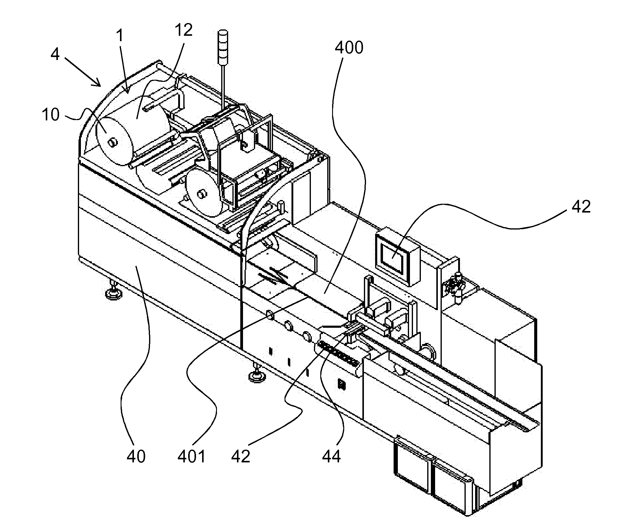
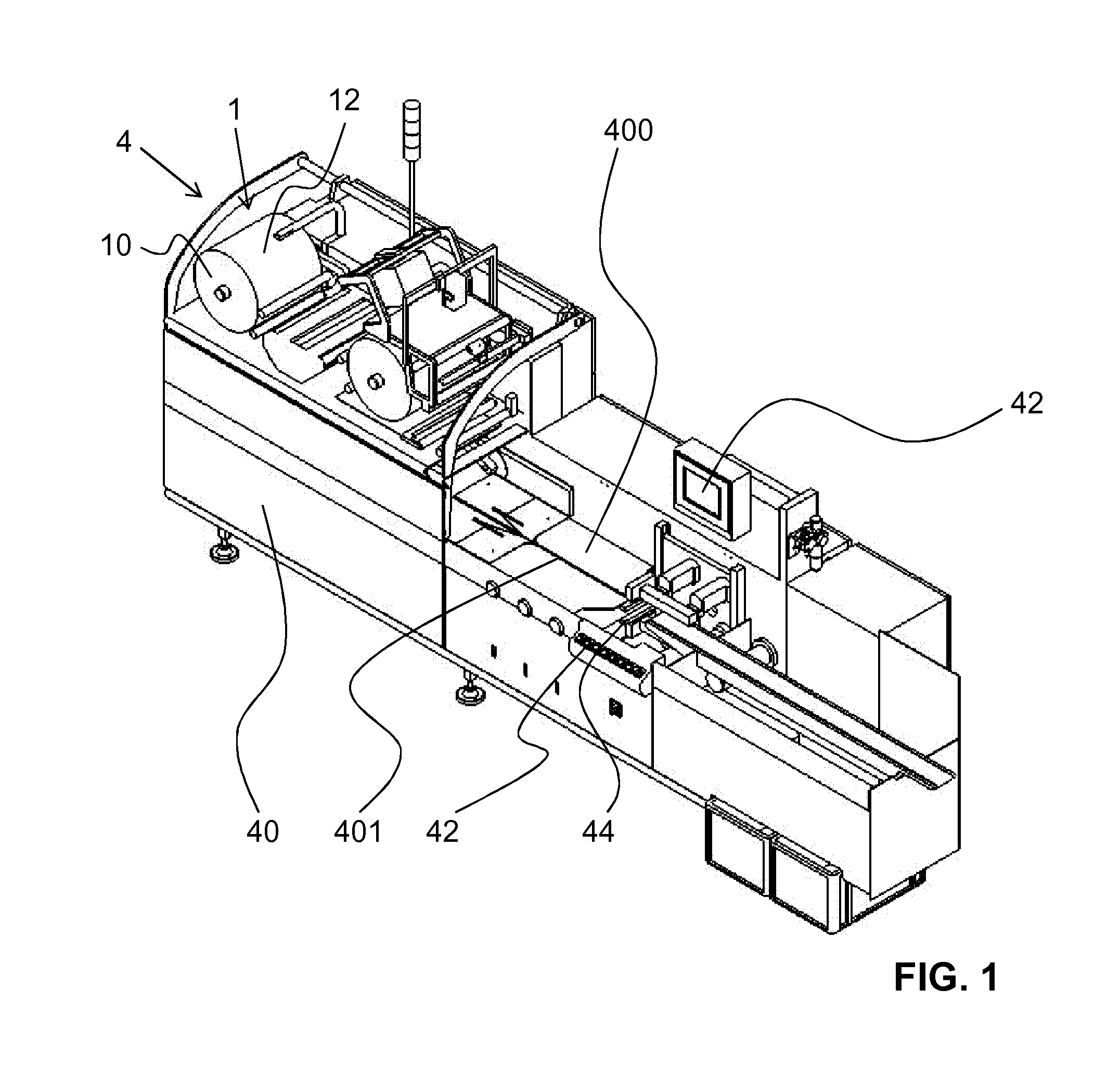
[0060]A horizontal tubular-bag machine is depicted in FIG. 1, as said machine is well known from the prior art. The tubular-bag machine 4 has a film roll 10 as packaging material 1. The film roll 10 contains a packaging sheet material 12.

[0061]The tubular-bag machine 4 comprises a frame 40 with operating and display elements 42 mounted thereon. A running surface 400, which has a longitudinal slot 401, is provided on the top side of the tubular-bag machine 4. The longitudinal slot 401 is used to accommodate the longitudinal sheet edge regions of the packaging sheet material 12 formed to a packaging tube during transport of the objects to be packaged along the longitudinal direction of the running surface 400. The tubular-bag machine 4 depicted in FIG. 1 furthermore comprises a longitudinal-connection device, which is not visible here and is disposed beneath the running surface 400, as well as a transverse-connection and separation device 44, which, in a known manner, welds the packag...


PUM

PropertyMeasurementUnit
widthaaaaaaaaaa
widthaaaaaaaaaa
widthaaaaaaaaaa

Abstract

The invention specifies an in particular horizontal tubular-bag machine (5) in which objects (2) which are provided for packaging are conveyed along a conveying direction (6) by means of a conveying apparatus (51). The tubular-bag machine (5) has an apparatus (50, 43) for producing from a packaging sheet material (12) a packaging tube (13) extending in the conveying direction (6), and also has a longitudinal-connection device (53, 54) and a transverse-connection device (44) for producing longitudinal and transverse connections in the packaging tube (13). Also provided is a gas-adjusting device (8) with an introduction head (80) for engaging in the packaging tube (13) in a direction transverse to the conveying direction, wherein the introduction head (80) has a first gas-passage opening (802, 804, 805, 807, 808) and at least one second gas-passage opening (802, 804, 805, 807, 808) by way of which a gas is fed into the packaging tube (13) or removed therefrom.

Description

BACKGROUND OF THE INVENTION[0001]The present invention relates to a tubular-bag machine having a gas-adjusting device. The gas-adjusting device is particularly used to remove air from a packaging tube formed by the tubular-bag machine and / or to feed gas into the packaging tube. The invention further relates to a gas-adjusting device and a method for adjusting the gas content of the packagings for such a tubular-bag machine.[0002]Tubular-bag machines are used in the packaging industry for packaging products in a packaging sheet material. It is thereby necessary to differentiate basically between horizontal and vertical tubular-bag machines.[0003]In the case of horizontal packaging machines, a packaging sheet material that is unwound from a reel and placed around products or product groups, which are supplied in a row, is formed to a tube which laterally encloses these products or product groups. The packaging tube and the products to be packaged are usually moved together and continu...

Claims


Application Information

Patent Timeline
Patent Type & Authority Applications(United States)
IPC IPC(8): B65B31/00B65B35/30B65B9/06
CPCB65B31/00B65B35/30B65B9/06B65B31/04B65B31/06B65B9/067B65B9/073
Inventor GRETHER, MICHAELWECKERLE, ROLANDEGLI, MARCEL
Owner ROBERT BOSCH GMBH
Why Eureka
Try Eureka