
Balanced turbine engine portion and turbine engine

Active Publication Date: 2016-10-06
SN DETUDE & DE CONSTR DE MOTEURS DAVIATION S N E C M A
View PDF5 Cites 0 Cited by
  • Summary
  • Abstract
  • Description
  • Claims
  • Application Information

AI Technical Summary

Benefits of technology

The invention provides a system for fastening balancing masses, such as nuts, to a turbomachine part without requiring a heavy crimping step. The system allows for easier positioning of fasteners and reduces the risk of damage to the turbomachine part during balancing. The system also facilitates maintenance operations as it does not require uncrimping fasteners one by one. An angular sector of a balancing ring enables multiple fasteners to be positioned at a time, saving time and effort for the technician.

Problems solved by technology

These high rotation speeds can cause significant vibrations of some turbomachine parts, wherein these vibrations can, in the short or medium term, damage said parts.
As a result, this step is tedious to implement, has considerable damage risks for the piece to be balanced and has a significant influence on the manufacturing time of a turbomachine.
This same system is not particularly adapted for maintenance operations either.
Indeed, this part is made of aluminum and thus has a high damage risk upon crimping and dismounting the nuts for fastening balancing screws.

Method used


Image

  • Balanced turbine engine portion and turbine engine
  • Balanced turbine engine portion and turbine engine
  • Balanced turbine engine portion and turbine engine

Examples


Embodiment Construction

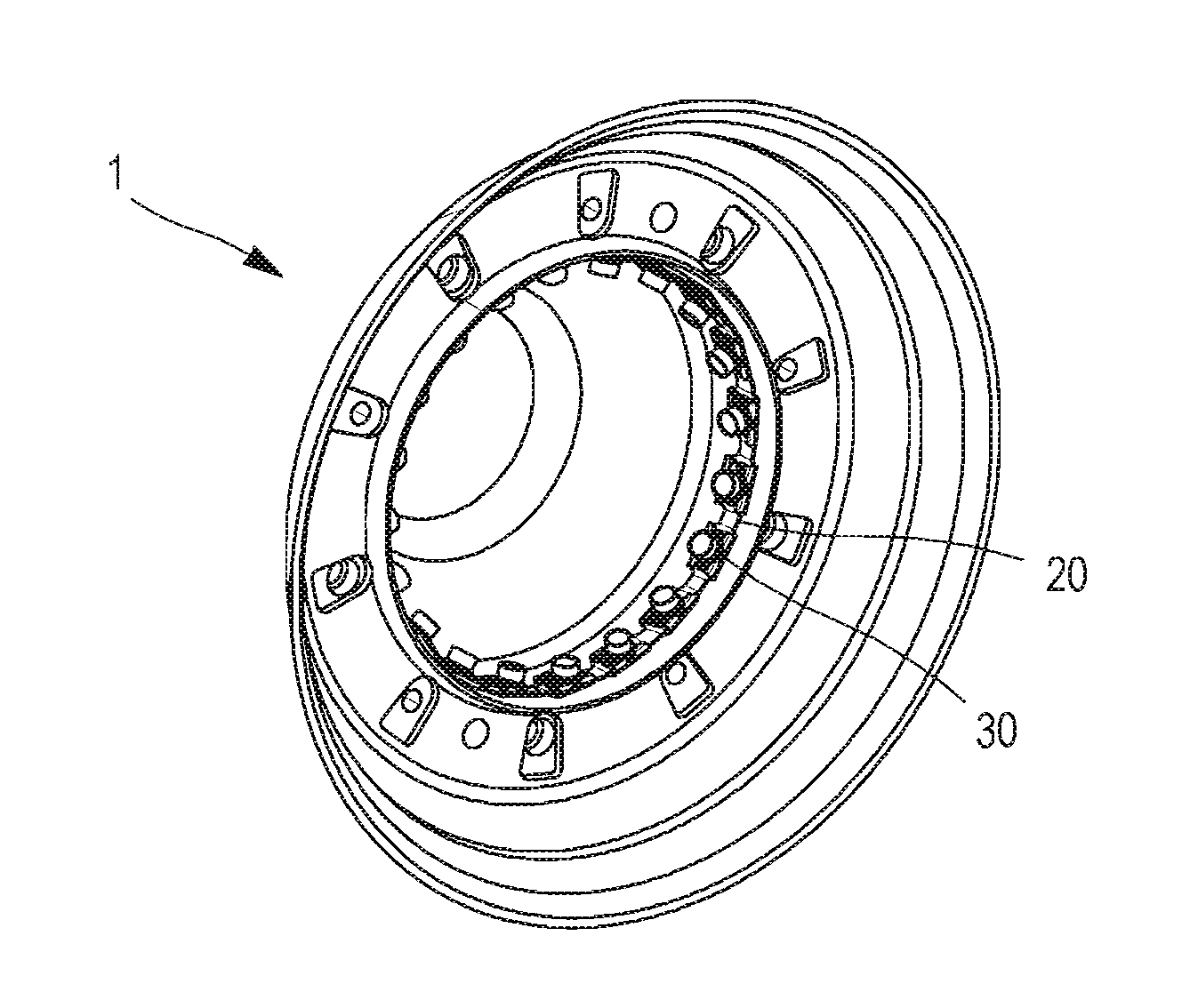
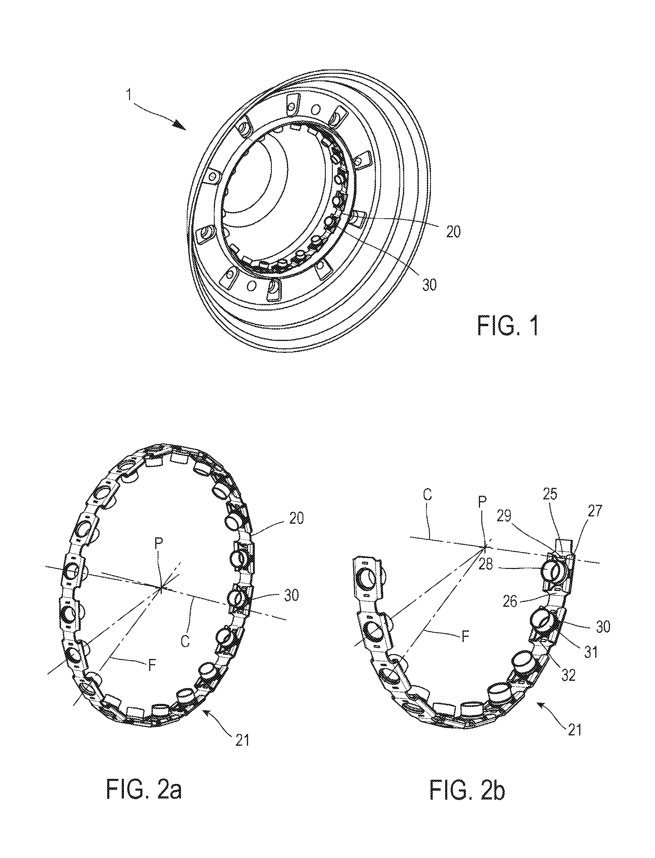
[0038]FIG. 1 illustrates a turbomachine inlet cone 1 equipped with a balancing ring 20 including a plurality of nuts 30 for fastening corresponding balancing screws 40, not illustrated in FIG. 1.

[0039]Such a balancing ring 20 is as illustrated in FIG. 2a, in the form of a strip the two ends of which are joined to have a substantially circular transverse cross-section. The balancing ring 20 thus has a substantially cylindrical revolution shape the height of which is in the same order of magnitude as the width of a nut 30. According to other possibilities of the invention, which are not illustrated, the balancing ring 20 can have a revolution shape other than a cylindrical one, such as a frustro-conical shape. The balancing ring 20 is centered about a ring axis (C).

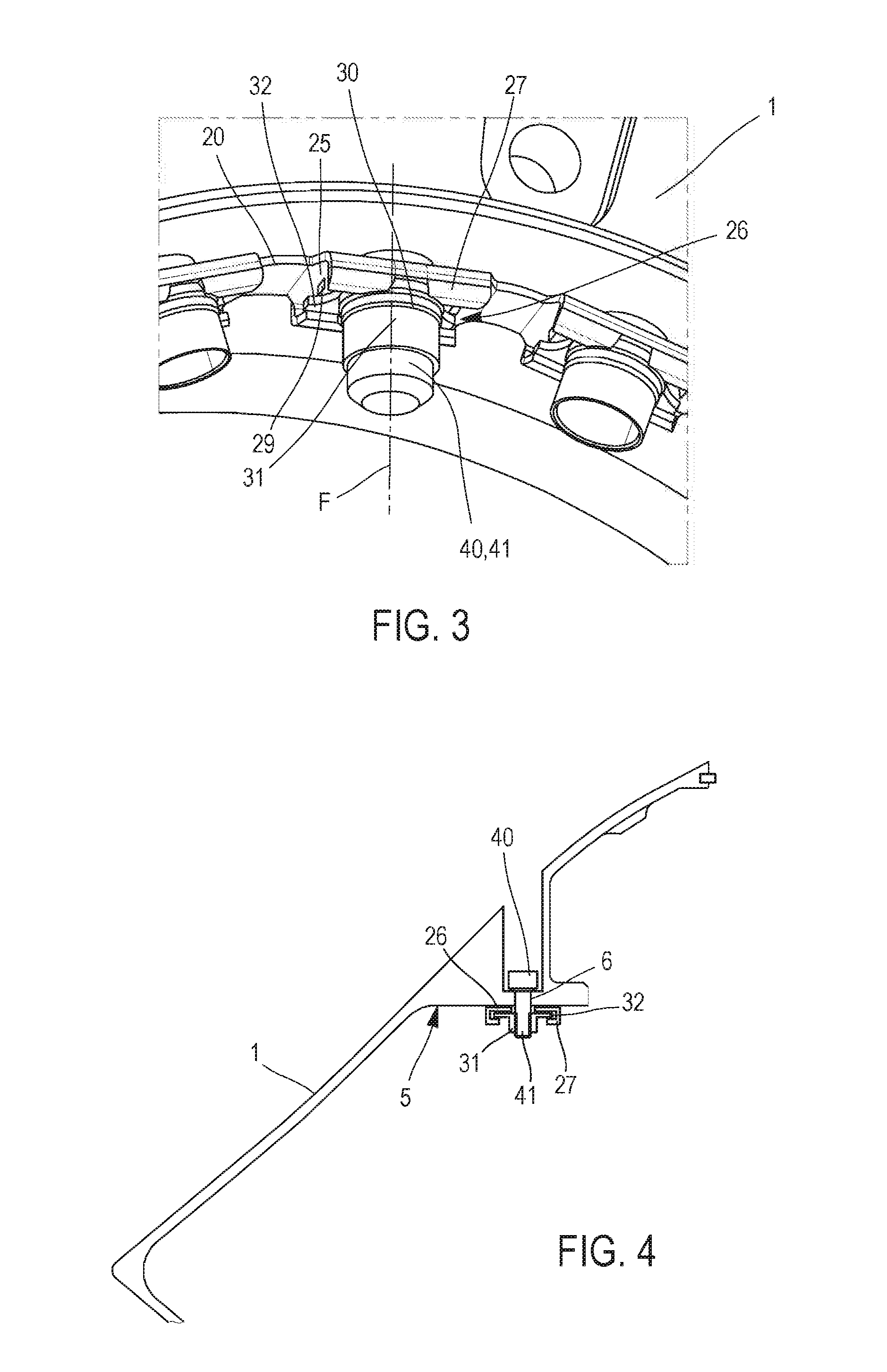
[0040]The balancing ring 20, as illustrated in FIG. 2b, can be formed from one or more angular sectors 21 having an angle between 20° and 360°. According to a preferred configuration illustrated in FIG. 2b, the balancing ri...


PUM


Abstract

A balanced turbomachine part including one angular sector arranged to form a balancing ring centered about a ring axis. The angular sector includes a plurality of fasteners, a bearing face having a complementary shape to the balancing ring, the angular sector bearing on the bearing face. The part further includes a plurality of balancing masses each fastened to the corresponding fastener of the angular sector, at least one of the balancing masses also acting as a fastener for fastening the angular sector on the bearing face.

Description

TECHNICAL FIELD[0001]The invention relates to the field of turbomachines and balancing some turbomachine parts.STATE OF PRIOR ART[0002]The turbomachines have, by definition, pieces rotating at relatively high speeds. These high rotation speeds can cause significant vibrations of some turbomachine parts, wherein these vibrations can, in the short or medium term, damage said parts. Therefore, it is necessary to balance said parts in order to limit the amplitude of these vibrations.[0003]Thus, it is known to provide on these turbomachine parts to be balanced, the fastening of balancing masses the distribution of which is suitable for balancing said parts.[0004]To provide such an fastening, the turbomachine part to be balanced includes a crimping groove adapted to receive nuts and the nuts can be crimped in this groove. The balancing masses take the form of balancing screws the mass of which is adapted by modifying the length.[0005]Upon balancing such a turbomachine part, the nuts are f...

Claims


Application Information

Patent Timeline
IPC IPC(8): F01D25/04F01D9/02F02C7/04
CPCF01D25/04F02C7/04F05D2230/60F05D2250/232F05D2260/96F01D9/02F01D5/027G01M1/36F16F15/34Y02T50/60
Inventor LE STRAT, JEAN-LUCPOHIER, HERVE
Owner SN DETUDE & DE CONSTR DE MOTEURS DAVIATION S N E C M A
Learn More