
Device and method for detecting an impact on a composite material structure

Active Publication Date: 2014-06-19
AIRBUS OPERATIONS SAS
View PDF7 Cites 13 Cited by
  • Summary
  • Abstract
  • Description
  • Claims
  • Application Information

AI Technical Summary

Benefits of technology

The patent describes a system that uses acoustic modules to record sound waves during a flight of an aircraft. These waves can then be analyzed by a processing unit to check and maintain the aircraft. The system is designed to be easy to install and remove, and can help evaluate the criticality of impacts on the aircraft's structure.

Problems solved by technology

Since this check has to be performed on all these elements, it is lengthy and tedious.
Moreover, it is not sufficient to carry out a visual check of these structural elements.
Indeed, a composite material structure that has received an impact may be damaged inside, for example by delamination, while exhibiting an exterior aspect similar to that of an intact structure.
According to a first drawback, this conventional ultrasound-based check remains a lengthy and tedious operation, the emitting probe having to be moved over all the exterior structural elements to be checked.
Moreover, certain zones of these exterior structural elements are difficult to access and therefore difficult to check.
According to another drawback, for certain levels of impact energy, accidental delaminations remain invisible with these conventional non-destructive checking means.
These additional plies increase the overall weight of the aircraft and penalize its performance.
Generally, the installation which is described in this document FR-2,937,953 is not suited to the detection of an impact on a composite material structure since it has been developed for sheet metal aircraft fuselages.
Therefore, it does not make it possible to detect impacts on the exterior structural elements when the aircraft is in flight.
Consequently, the entirety of the detection installation must be integrated into the aircraft right from its design and its assembly, thereby preventing any use of this installation on existing aircraft, without dismantling numerous elements and providing numerous hours of labor.

Method used


Image

  • Device and method for detecting an impact on a composite material structure
  • Device and method for detecting an impact on a composite material structure

Examples


Embodiment Construction

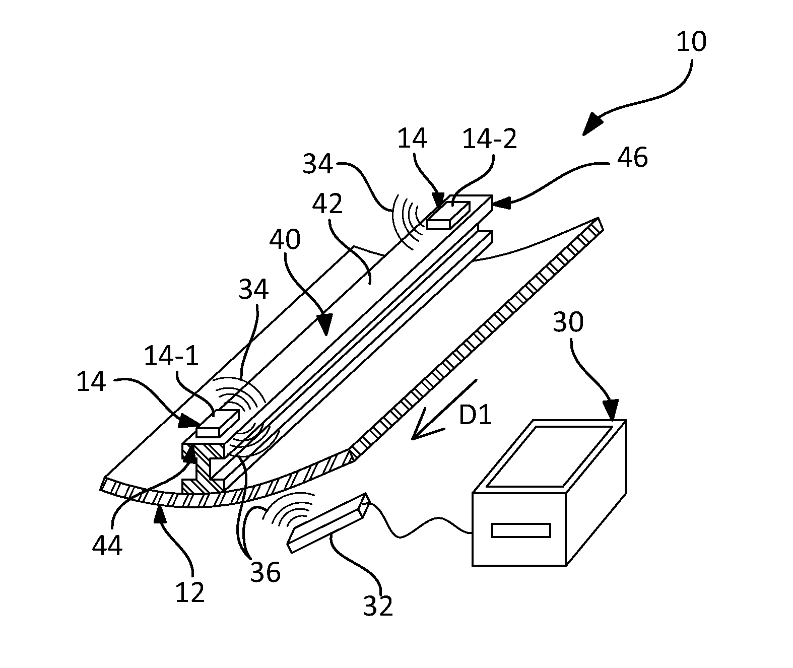
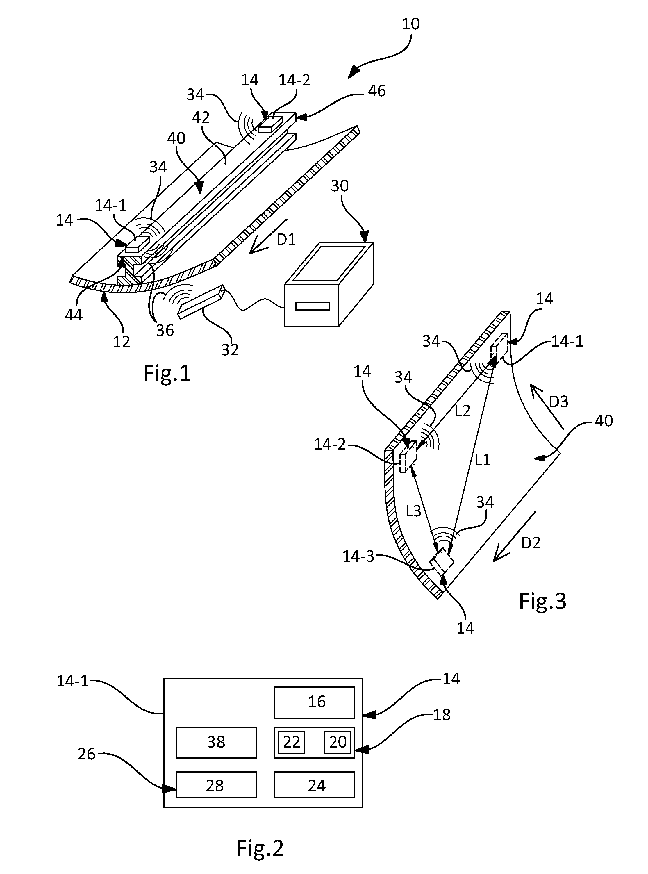
[0053]As illustrated by FIG. 1, the present invention relates to a device 10 for detecting an impact on a composite material structure 12.

[0054]The detection device 10 comprises at least two acoustic modules 14 intended to be secured to the composite material structure 12, and a processing unit 30 able to communicate remotely with each of the acoustic modules 14.

[0055]As illustrated schematically by FIG. 2, each acoustic module 14 comprises an acoustic sensor 16.

[0056]Thus, each acoustic module 14 is capable of sensing the sound wave (or waves), especially of Dirac type, generated by an impact on the structure 12 and propagating in this structure 12.

[0057]In a first variant, the acoustic sensor 16 is of piezoelectric type.

[0058]In a second variant, the acoustic sensor 16 is of electromagnetic type and comprises for example a solenoid with a central magnet.

[0059]According to the invention, each acoustic module 14 is electrically autonomous.

[0060]Thus, since no wired link has to be pr...


PUM


Abstract

A device for detecting an impact on a composite material structure. This detection device comprises at least two acoustic modules intended to be secured to the composite material structure and a processing unit able to communicate remotely with each of the acoustic modules. Each acoustic module is electrically autonomous and comprises its own means for recording the sound waves sensed by its acoustic sensor. An aircraft structure is also provided comprising a composite material structural element equipped with the impact detection device. A method is also provided for detecting an impact on a composite material aircraft structural element equipped with an impact detection device.

Description

CROSS-REFERENCES TO RELATED APPLICATIONS[0001]This application claims the benefit of the French patent application No. 12 62207 filed on Dec. 18, 2012, the entire disclosures of which are incorporated herein by way of reference.BACKGROUND OF THE INVENTION[0002]The present invention relates to a device and to a method for detecting an impact on a composite material structure.[0003]Composite materials are widely used in aeronautics, including for making the elements of the primary structure of the aircraft constituting the fuselage.[0004]During a flight, or while the aircraft is being parked, these exterior structural elements are apt to undergo diverse impacts.[0005]It is therefore necessary to undertake a check of these exterior structural elements regularly, and preferably before each new use of the aircraft.[0006]This check is performed by searching for any damage due to impacts on these structural elements.[0007]Since this check has to be performed on all these elements, it is le...

Claims


Application Information

Patent Timeline
IPC IPC(8): G01N29/04
CPCG01N29/04G01N29/045G01N29/2475G01N29/2481G01N2291/0231G01N2291/2694
Inventor CHAUME, OLIVIERKERN, XAVIERCABOT, JEAN-PASCAL
Owner AIRBUS OPERATIONS SAS
Learn More