Portable electronic equipment and method of controlling a portable electronic equipment

a technology of electronic equipment and portable devices, applied in the direction of television systems, instruments, image enhancement, etc., can solve the problems of erroneous identification of objects by users, low accuracy of gaze tracking, and high accuracy of dedicated gaze tracking devices, and achieve the effect of small resolution

Active Publication Date: 2016-10-06
SONY CORP
View PDF5 Cites 27 Cited by
  • Summary
  • Abstract
  • Description
  • Claims
  • Application Information

AI Technical Summary

Benefits of technology

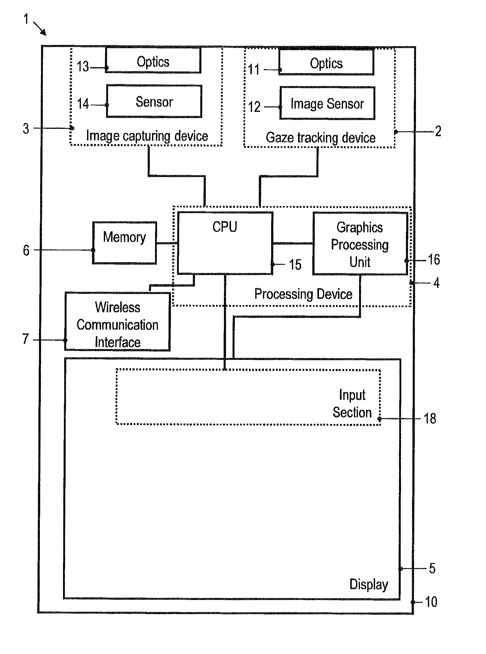
[0005]There is a need in the art for a portable electronic equipment and a method of controlling a portable electronic equipment which mitigate at least some of these shortcomings. There is in particular a need in the art for a portable electronic equipment and a method of controlling a portable electronic equipment in which the point of interest of a user may be determined more reliable even when the gaze tracking device has a small resolution.

Problems solved by technology

For many portable electronic devices, such as handheld cellular communication terminals or head-mounted devices, gaze tracking may be less accurate.
The reasons for this are that highly accurate, dedicated gaze tracking devices may not be attractive for portable electronic devices due to the costs and installation space requirements associated with such devices.
The spatial resolution of gaze tracking which can be attained with current low-cost solutions for gaze tracking in portable electronic devices may be prone to an erroneous identification of the object the user actually is interested in.
The low resolution of conventional inexpensive gaze tracking devices may reduce the user experience because it is prone to errors when detecting the points of interest, while more accurate dedicated gaze tracking devices may add to the costs of the equipment in a manner which makes them unattractive for many users.

Method used


Image

  • Portable electronic equipment and method of controlling a portable electronic equipment
  • Portable electronic equipment and method of controlling a portable electronic equipment
  • Portable electronic equipment and method of controlling a portable electronic equipment

Examples


Embodiment Construction

[0047]In the following, embodiments of the invention will be described in detail with reference to the accompanying drawings. It is to be understood that the following description of embodiments is not to be taken in a limiting sense. The scope of the invention is not intended to be limited by the embodiments described hereinafter or by the drawings, which are taken to be illustrative only.

[0048]The drawings are to be regarded as being schematic representations, and elements illustrated in the drawings are not necessarily shown to scale. Rather, the various elements are represented such that their function and general purpose become apparent to a person skilled in the art. Any connection or coupling between functional blocks, devices, components or other physical or functional units shown in the drawings or described herein may also be implemented by an indirect connection or coupling. Functional blocks may be implemented in hardware, firmware, software or a combination thereof.

[004...


PUM


Abstract

A portable electronic equipment comprises a gaze tracking device configured to track an eye gaze direction of a user in a time interval. The portable electronic equipment comprises a processing device coupled to the gaze tracking device and configured to generate heat map data for the eye gaze direction, generate saliency map data for a field of view of the user, and identify at least one point of interest in the field of view based on both the heat map data and the saliency map data.

Description

TECHNICAL FIELD[0001]Embodiments of the invention relate to a portable electronic equipment and to a method of controlling a portable electronic equipment. Embodiments of the invention relate in particular to portable electronic equipments which comprise a gaze tracking device operable to track an eye gaze direction of a user of the portable electronic equipment and methods of operating such portable electronic equipments.BACKGROUND ART[0002]Gaze based control continues to evidence increased popularity for a wide variety of electronic devices. In dedicated special application apparatuses, such as gaze based control in aircraft or surveillance applications, dedicated gaze tracking device may be operable to determine the eye gaze direction with a high accuracy.[0003]For many portable electronic devices, such as handheld cellular communication terminals or head-mounted devices, gaze tracking may be less accurate. The reasons for this are that highly accurate, dedicated gaze tracking de...

Claims


Application Information

Patent Timeline
Patent Type & Authority Applications(United States)
IPC IPC(8): G06F3/01G06T7/00H04N5/232G06K9/00
CPCG06F3/013G06K9/00604G06T7/0044G06T2207/30241H04N5/23219H04N5/23212G06T2207/30201H04N5/23216G06F3/04842G06T7/74G06V40/19H04N23/61H04N23/631H04N23/635H04N23/62H04N23/611
Inventor THORN, OLAARONSSON, PAR-ANDERS
Owner SONY CORP
Why Eureka
Try Eureka