Video enhancing device and method

a technology of video enhancement and radar, applied in the field of video processing, can solve the problems of difficulty in discerning a small target in a highly fluctuating and noisy environment, and inability to efficiently distinguish low rcs and slow moving targets from stationary clutter. , to achieve the effect of easy discerning low rcs

Inactive Publication Date: 2016-10-06
THALES NEDERLAND BV
View PDF2 Cites 5 Cited by
  • Summary
  • Abstract
  • Description
  • Claims
  • Application Information

AI Technical Summary

Benefits of technology

[0013]The invention accordingly provides a time-extrapolated easeful video enhancing device capable of creating a smooth and low eye-strain display video stream from radar signal data to help the radar operator assess the environment and more easily discern low RCS and slow moving objects which may be of interest.

Problems solved by technology

However, data processing does not allow to efficiently distinguish low RCS and slow moving targets from stationary clutter.
Indeed, a surface object, such as for example a swimmer in the sea, might be missed as a wanted target, due to its characteristics not being tracked by the radar system.
Discerning a small target in a highly fluctuating and noisy environment becomes therefore difficult.
This limitation is especially significant for surveillance radar systems which have scan times of one second or a few seconds.
Accordingly, the refresh rate of the image hinders the operators' ability to distinguish small and slow moving targets from clutter and noise.
The solution consisting of coupling track information to the display video presents a number of drawbacks so that very few radar systems resort to this approach and even keep the display video unprocessed and displayed at the low refresh rate.
A major limitation of this approach lies on the fact that the tracking is primarily designed for non-stationary objects (such as for example jets, airliner, missiles, shells) and is not optimized for low RCS and slow moving objects.
As a result, these specific objects are not recognized and tracked.
However, in case of strong maneuvering targets or high noise conditions, the predictions are not precise enough, thereby jeopardizing the cross-checking capacity.
Another limitation of this approach is due to the fact that a feedback loop implies constraints on implementation and timing.
Even in situations where the tracking process is capable of tracking slow moving and low RCS objects, a fundamental problem thus exists.
More specifically, since radar signals are highly fluctuating and very disturbed by noise, the resulting video signal from a low RCS object may change a lot from scan to scan.
This generally causes eye strain and cannot result in a smooth image over multiple scans due to the jump at scan changes.
Such solution thus only helps the operator within a scan time interval and not over multiple scans.

Method used


Image

  • Video enhancing device and method
  • Video enhancing device and method
  • Video enhancing device and method

Examples


Embodiment Construction

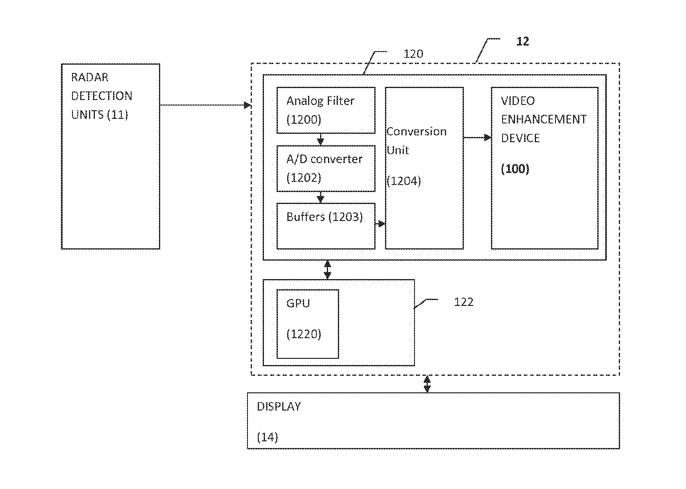
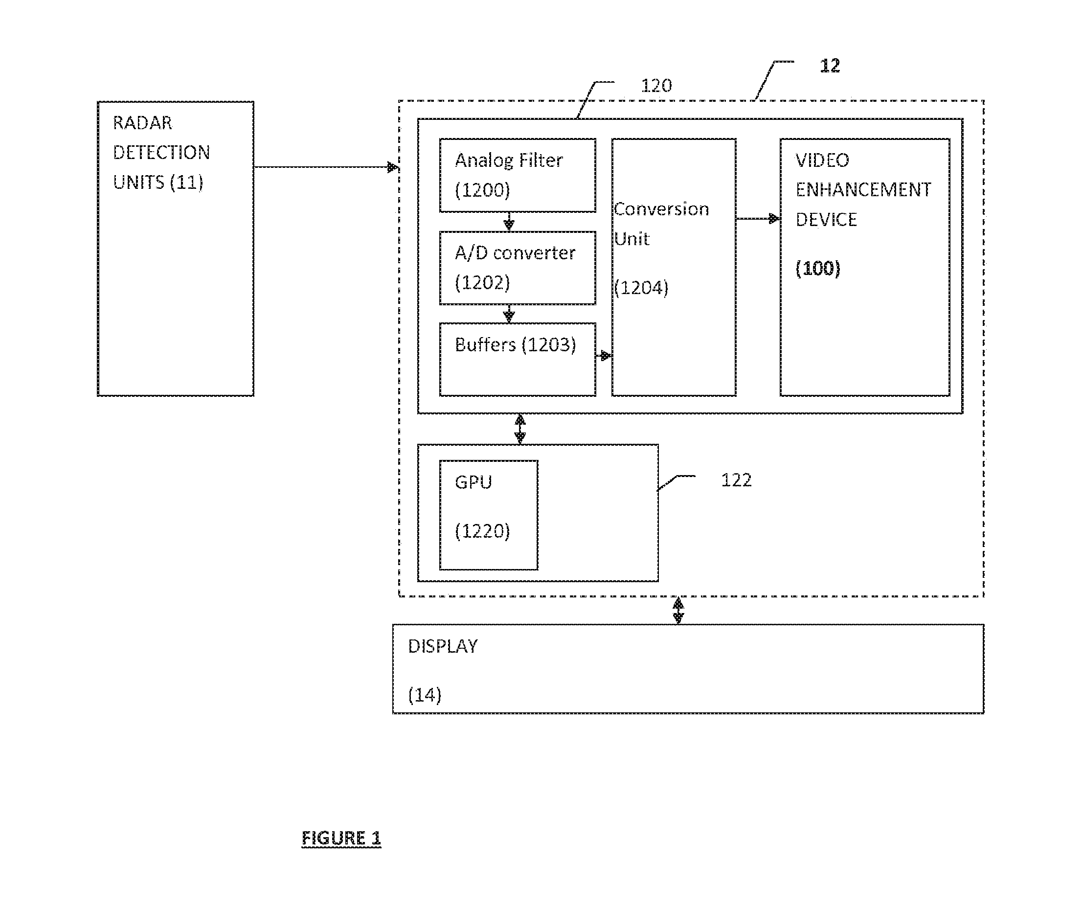
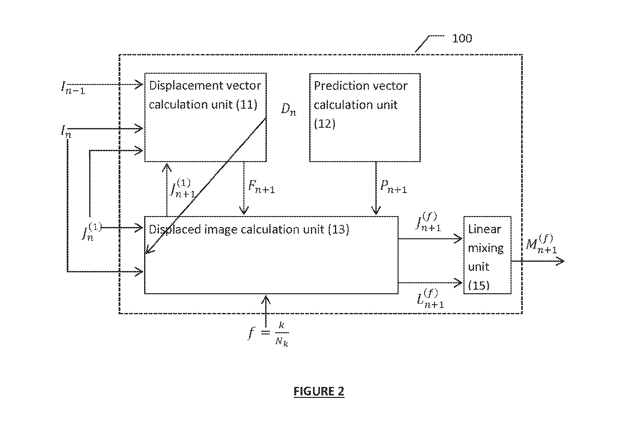
[0023]Referring to FIG. 1, there is shown an exemplary implementation of a video enhancing device 100 according to certain embodiments of the invention.

[0024]The video enhancing device 100 is configured to receive two images In and In−1 corresponding to two successive scans captured by a video surveillance system 1. More specifically, the video enhancing device 100 is further configured to output the next scan In+1 from the two successive scans corresponding to the previous scan In−1 and the current scan In.

[0025]Even if the invention is not limited to such applications, the invention has particular advantages for the surveillance and detection of slow moving objects, such as for example a swimmer in the sea. In a preferred embodiment of the invention, the video surveillance system 1 may be a radar surveillance system. The following description will be made with reference to such a radar application. However, the skilled person will readily understand that the invention may be used ...


PUM


Abstract

A method for enhancing video display of a video surveillance system, comprises: a. receiving a first video image In−1 and a second video image In corresponding to a previous scan n−1 and a current scan n of the video surveillance system, b. determining a backwards displacement vector Dn from image In associating with scan n to image In−1 associated with scan n−1; c. determining a predicted image Jn+1 for scan n+1 based on the backward displacement vector Dn and on the image In corresponding to the current scan n. The method further comprises displaying an image based on the predicted image.

Description

FIELD OF INVENTION[0001]The invention generally relates to video processing, and particularly to a method and a device for enhancing radar video.BACKGROUND ART[0002]In many technological fields, there is a need for detecting specific objects (also referred to as “targets”) and generating a video rendering of the detected targets and of the environment for “situational awareness”.[0003]In particular, radar systems are used to detect targets by transmitting a Radio Frequency (RF) signal with specific characteristics and receiving the emitted signal perturbed by the environment after reflection from the target in this environment. The transmitted RF signal can be bundled in a specific direction, either by using a particular antenna design or by signal processing (i.e., digital beamforming). A similar approach can be used for the received signal. Bundling the signals in specific directions results in a higher gain, which allows the detection of objects at larger ranges.[0004]Signal and ...

Claims


Application Information

Patent Timeline
Patent Type & Authority Applications(United States)
IPC IPC(8): G06T7/20G01S7/06G01S7/10
CPCG06T7/20G01S7/10G01S7/064G06T2207/10016G06T2207/30232G01S7/068G01S13/583
Inventor KAMPMAN, JORIS E.J.J.KÖHLER, OLAF O.M.
Owner THALES NEDERLAND BV
Why Eureka
Try Eureka