

Cooler for secondary battery
- Summary
- Abstract
- Description
- Claims
- Application Information
AI Technical Summary
Benefits of technology
Problems solved by technology
Method used
Image

Examples
Embodiment Construction
[0074]Hereinafter, coolers for a secondary battery according to exemplary embodiments of the present invention will be described with reference to the accompanying drawings.
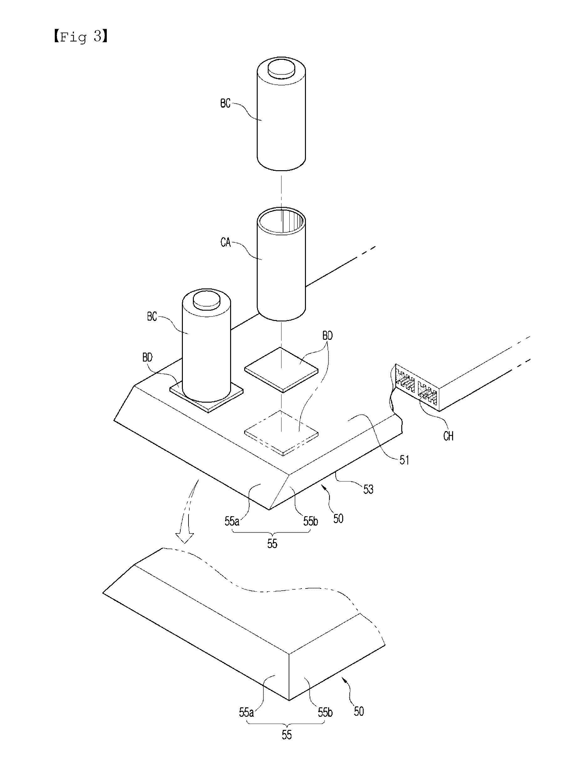
[0075]A cooler for a secondary battery according to an embodiment of the present invention includes, as shown in FIG. 3, a heat-dissipating member 50 and a backup member to be described below.
[0076]The heat-dissipating unit 50, as shown in FIG. 3, has a battery cell BC or a cell case CA where a battery cell BC is disposed. In the heat-dissipating member 50, as shown in the figure, a cylindrical bar-shaped battery cell BC may be vertically disposed, or a common battery cell (not shown) may be vertically or horizontally disposed.
[0077]Heat generated when the battery cell BC is discharged is transmitted to a first surface of the heat-dissipating member 50 and is dissipated through a second surface. For example, when the heat-dissipating member 50 includes a battery cell BC or a cell case CA on the first surface, as ...
PUM
 Abstract
Description
Claims
Application Information