Piezoelectric vibrator and frequency adjustment method for piezoelectric vibrator

a frequency adjustment and piezoelectric technology, applied in the direction of impedence networks, electrical apparatus, etc., can solve the problems of low q-value, high precision, and risk of short circuit, and achieve the effect of low strength drop, high q-value, and high precision

Active Publication Date: 2016-10-06
MURATA MFG CO LTD
View PDF2 Cites 2 Cited by
  • Summary
  • Abstract
  • Description
  • Claims
  • Application Information

AI Technical Summary

Benefits of technology

[0021]According to the piezoelectric vibrator and the frequency adjustment method for the piezoelectric vibrator according to the present invention, when the frequency adjustment is carried out, an effect on a surface of the piezoelectric vibrator is unlikely to be generated, the electrode is unlikely to scatter, and a residual substance is also unlikely to be generated. This makes it possible to adjust a frequency with high precision. In addition, a drop in the strength due to the frequency adjustment is small. Moreover, a piezoelectric vibrator having a high Q-value as well as stable characteristics can be provided.

Problems solved by technology

Further, when the mass film having reattached is gasified over time, a variation in frequency or the like occurs to make the characteristics likely to be unstable.
Furthermore, there is a risk of a short circuit in the case where the mass film is attached between electrode patterns.
As such, in the case where the residual substance is attached to a section of vibration, the vibration is obstructed and there arises a risk of a Q-value being lowered, especially at a time of large amplitude driving.
With the method in Patent Document 2, providing a projection on the inner wall of the package makes a height of the package larger and raises a problem that a quartz vibration device becomes large in size.
In addition, even if the projection is provided on the inner wall of the package, in the case where a gasified adjustment film moves within the package, the stated gasified film cannot be completely prevented from reattaching to the quartz tuning fork vibrator.
With the method in Patent Document 3, providing an alteration layer in the vibration arm is likely to lower the strength of the vibration arm.

Method used


Image

  • Piezoelectric vibrator and frequency adjustment method for piezoelectric vibrator
  • Piezoelectric vibrator and frequency adjustment method for piezoelectric vibrator
  • Piezoelectric vibrator and frequency adjustment method for piezoelectric vibrator

Examples


first embodiment

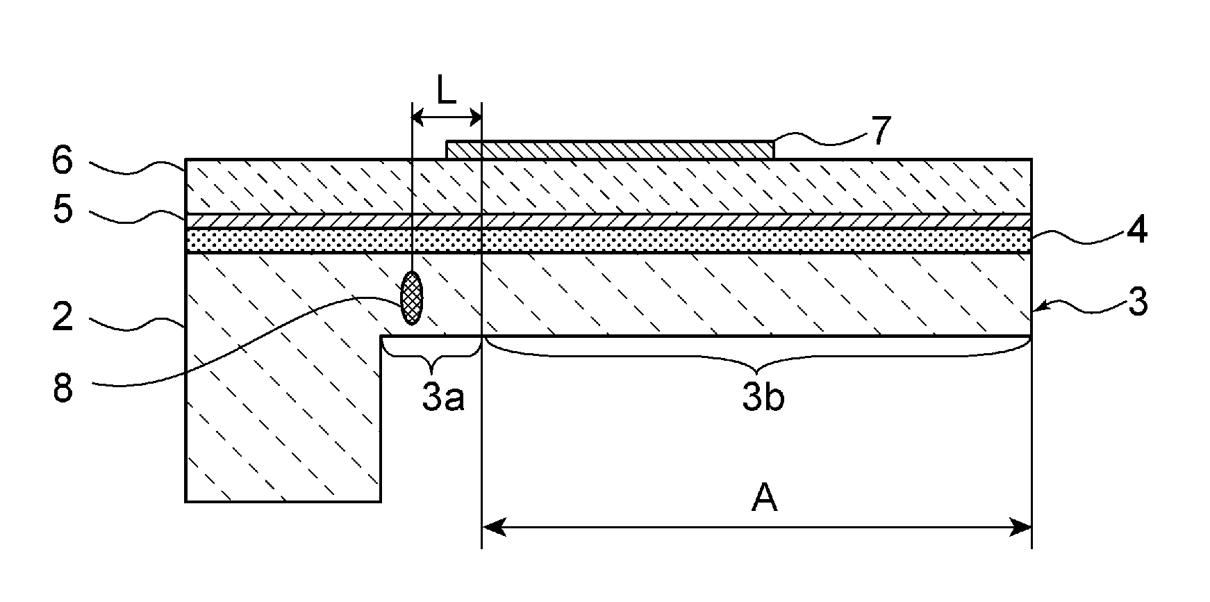
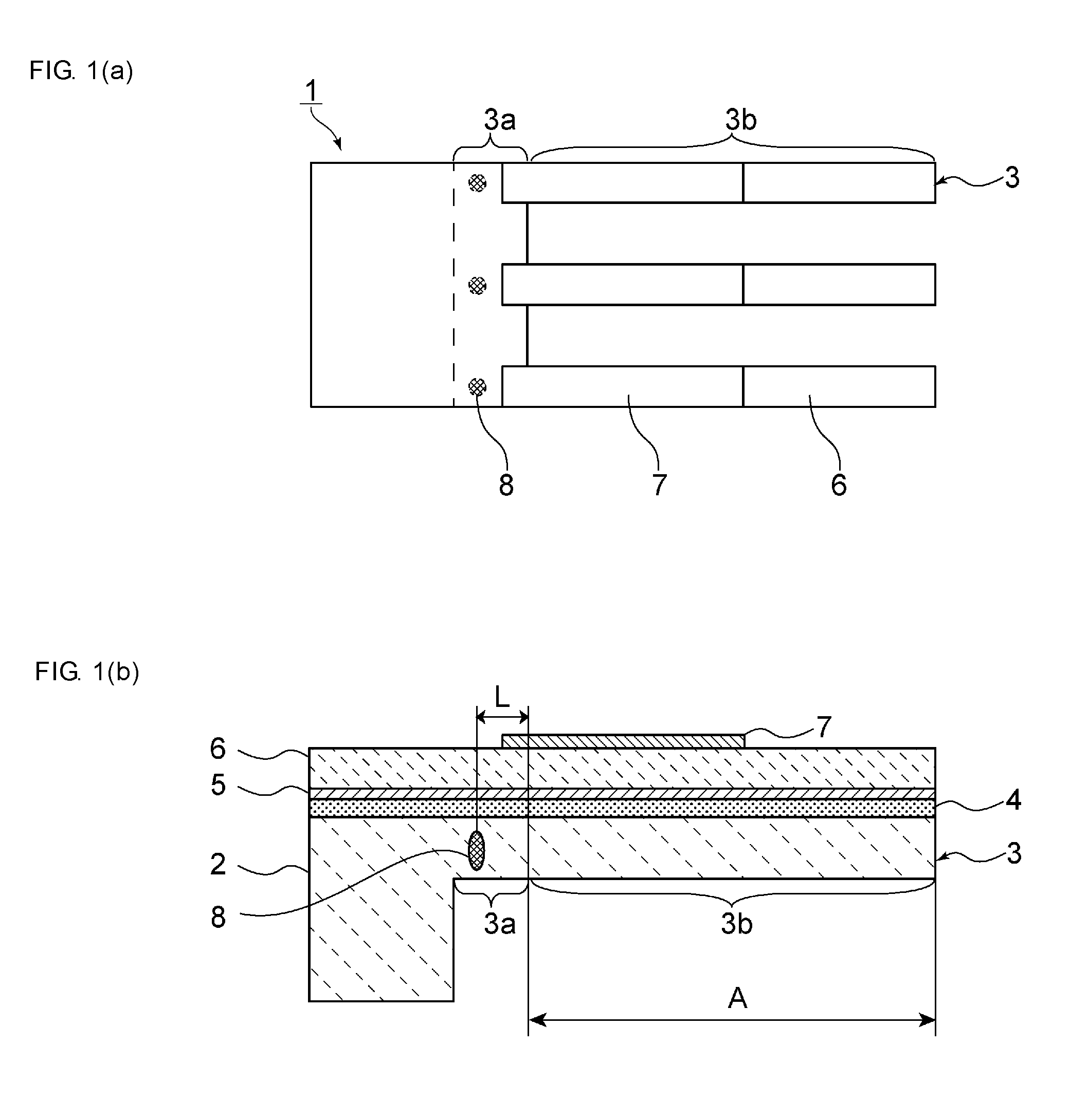
[0026]FIG. 1(a) is a plan view of a piezoelectric vibrator according to a first embodiment of the present invention, and FIG. 1(b) is a cross-sectional side view of the piezoelectric vibrator according to the present invention.

[0027]As shown in FIGS. 1(a) and 1(b), a piezoelectric vibrator 1 includes a base portion 2 and a vibration arm 3 connected to the base portion 2. The vibration arm 3 includes a connection portion 3a connected to the base portion 2, and a plurality of vibration arm main bodies 3b extending in parallel with each other from the connection portion 3a. Each of the vibration arm main bodies 3b is formed in a strip shape extending in a lengthwise direction. One end of each vibration arm main body 3b is connected to the connection portion 3a. The connection portion 3a extends in a width direction of the vibration arm main bodies 3b and these vibration arm main bodies 3b are connected to the connection portion 3a. A thickness of the connection portion 3a is equal to a...

second embodiment

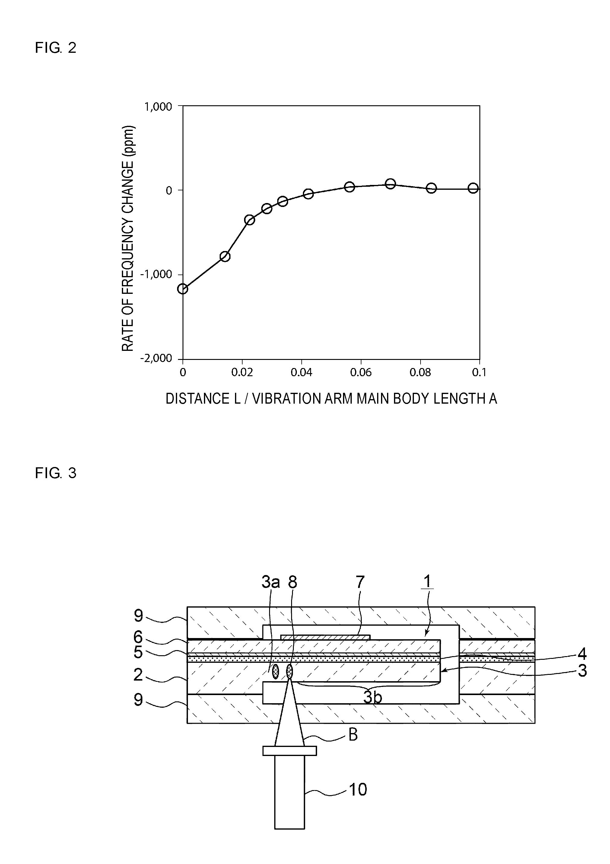
[0044]FIG. 3 is a schematic cross-sectional side view illustrating a frequency adjustment method for a piezoelectric vibrator according to the present invention.

[0045]In this embodiment, the connection portion 3a is irradiated with a laser beam B in a state where the piezoelectric vibrator 1 is sealed with a package material 9. To be more specific, the laser beam B is radiated from a laser oscillator 10 installed on a side opposite to the surface of the connection portion 3a where the lower electrode 5 is formed. By setting the focal point of the laser beam B to a location inside the connection portion 3a by using a lens or the like, the frequency of the piezoelectric vibrator 1 can be adjusted even in a state where the piezoelectric vibrator 1 is sealed. Through this, the alteration portion 8 can be provided inside the connection portion 3a without the radiated laser beam B passing through the upper electrode 7, the piezoelectric thin film 6, and the lower electrode 5. As such, inf...


PUM


Abstract

A frequency adjustment method is provided in which a residual substance is unlikely to be generated, the frequency can be adjusted with high precision, and a decrease in strength is made small.
A frequency adjustment method for a piezoelectric vibrator includes preparing the piezoelectric vibrator having a base portion, a vibration arm that includes a connection portion connected to the base portion as well as vibration arm main bodies extending from the connection portion and that is made of a single crystal, a lower electrode formed on the vibration arm, a piezoelectric thin film formed on the lower electrode, and an upper electrode formed on the piezoelectric thin film; and forming an alteration portion by irradiating the connection portion with a laser beam.

Description

CROSS REFERENCE TO RELATED APPLICATIONS[0001]The present application is a continuation of PCT / JP2014 / 080641 filed Nov. 19, 2014, which claims priority to Japanese Patent Application No. 2013-272370, filed Dec. 27, 2013, the entire contents of each of which are incorporated herein by reference.FIELD OF THE INVENTION[0002]The present disclosure relates to a piezoelectric vibrator using a piezoelectric thin film and a frequency adjustment method for a piezoelectric vibrator.BACKGROUND OF THE INVENTION[0003]Currently, there exist a variety of methods for adjusting a frequency of a piezoelectric vibrator having a plurality of vibration arms.[0004]In a frequency adjustment method disclosed in Patent Document 1 cited below, a piezoelectric vibrator disposed in a package is irradiated with a femtosecond laser. This makes it possible to remove a mass film or a base material of the piezoelectric vibrator so as to adjust the frequency while suppressing damage to the package. A wave length of t...

Claims


Application Information

Patent Timeline
Patent Type & Authority Applications(United States)
IPC IPC(8): H03H9/15H03H3/04
CPCH03H9/15H03H2003/0421H03H3/04H03H3/0077H03H9/215H03H9/2457H03H2003/0492
Inventor UNAMI, TOSHIHIKOKAMEDA, EITARO
Owner MURATA MFG CO LTD
Why Eureka
Try Eureka