Method for sensing fraudulent frames transmitted to in-vehicle network

Active Publication Date: 2016-10-06
PANASONIC INTELLECTUAL PROPERTY CORP OF AMERICA
View PDF2 Cites 25 Cited by
  • Summary
  • Abstract
  • Description
  • Claims
  • Application Information

AI Technical Summary

Benefits of technology

[0009]One non-limiting and exemplary embodiment provides a fraud-sensing electronic control unit (fraud-sensing ECU) for efficient sensing of a fraudulent message to be transmitted to a bus, in order to, for example, reduce consumption of an in-vehicle battery, in an in-vehicl

Problems solved by technology

Incidentally, a connection of a fraudulent node to a bus in an in-vehicle network and a fraudulent transmiss

Method used


Image

  • Method for sensing fraudulent frames transmitted to in-vehicle network
  • Method for sensing fraudulent frames transmitted to in-vehicle network
  • Method for sensing fraudulent frames transmitted to in-vehicle network

Examples


first embodiment

[0073]An embodiment of the present disclosure will now be described with reference to the drawings in the context of an in-vehicle network system 10 including a fraud-sensing ECU that implements an anti-fraud method for preventing a process based on a fraudulent frame from being executed on any other node (ECU) by using message IDs.

1.1 Overall Configuration of In-Vehicle Network System 10

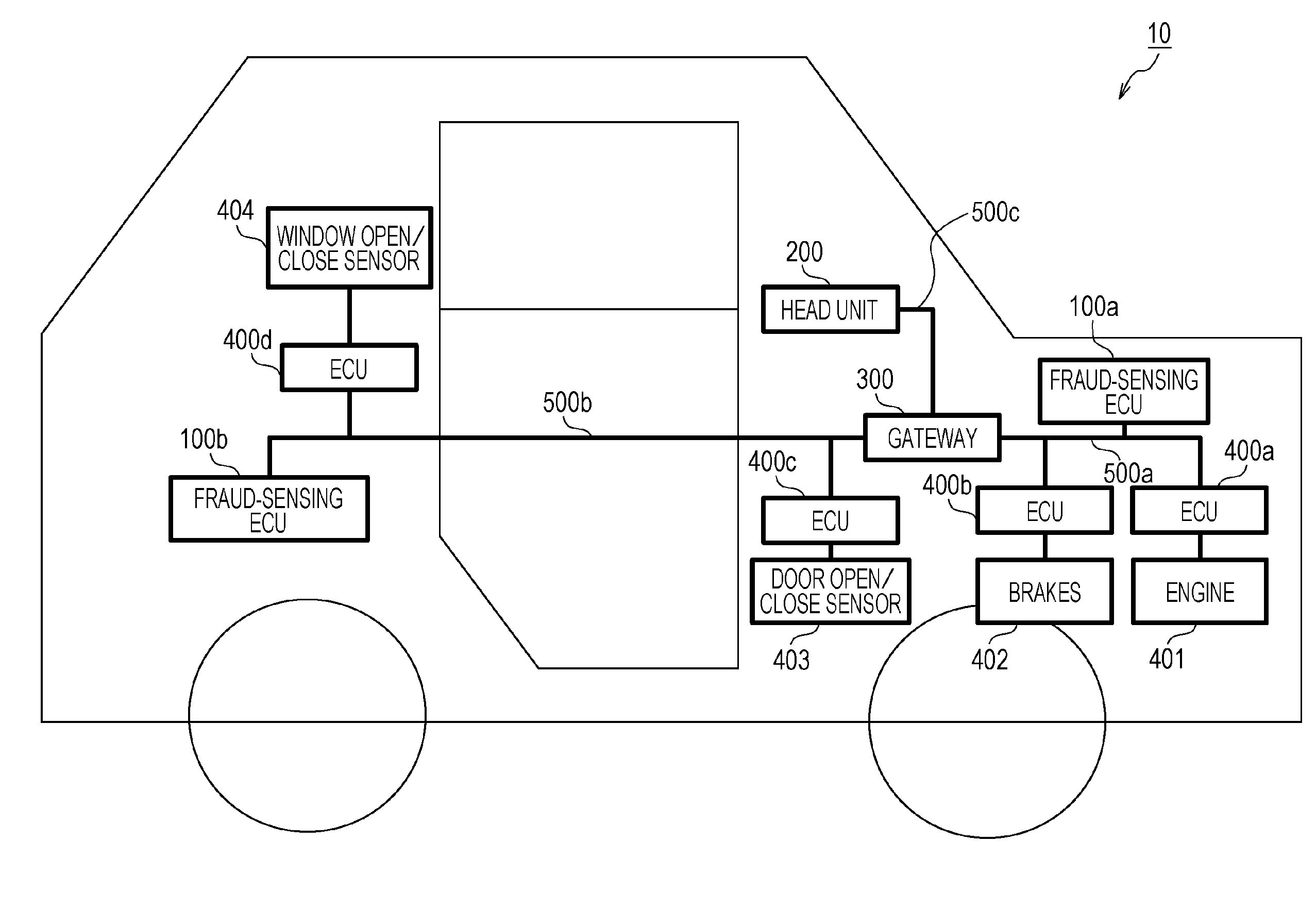
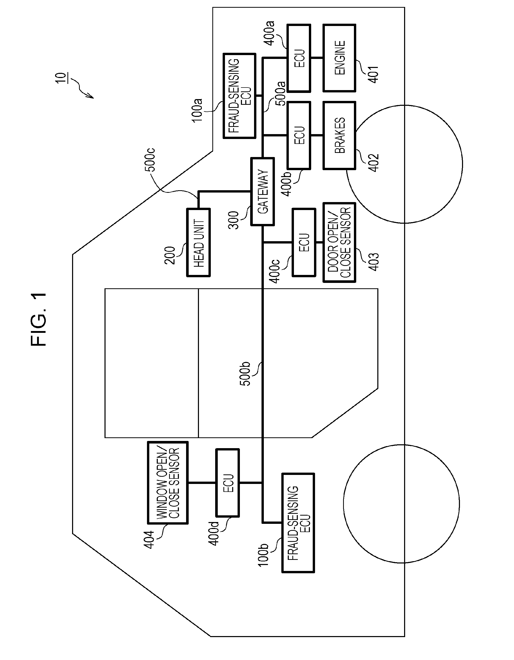
[0074]FIG. 1 is a diagram illustrating an overall configuration of an in-vehicle network system 10 according to a first embodiment. The in-vehicle network system 10 is an example of a network communication system in which communication is established in accordance with the CAN protocol, and is a network communication system in an automobile provided with various devices such as a control device and a sensor. The in-vehicle network system 10 is configured to include buses 500a to 500c, fraud-sensing ECUs 100a and 100b, a head unit 200, a gateway 300, and nodes connected to the buses, called ECUs, suc...

second embodiment

[0155]An embodiment of the present disclosure will now be described in the context of an in-vehicle network system 11 including a fraud-sensing ECU that implements an anti-fraud method for preventing a process based on a fraudulent frame from being executed on any other node (ECU) on the basis of a data range allowed for each message ID.

2.1 Overall Configuration of In-Vehicle Network System 11

[0156]FIG. 19 is a diagram illustrating an overall configuration of an in-vehicle network system 11 according to a second embodiment. The in-vehicle network system 11 is obtained by partially modifying the in-vehicle network system 10 illustrated in the first embodiment. The in-vehicle network system 11 is configured to include buses 500a to 500c, fraud-sensing ECUs 2100a and 2100b, a head unit 200, a gateway 300, and nodes connected to the buses, called ECUs, such as ECUs 400a to 400d connected to various devices. Of the constituent elements of the in-vehicle network system 11, constituent ele...

third embodiment

[0175]An embodiment of the present disclosure will now be described in the context of an in-vehicle network system 12 including a fraud-sensing ECU that implements an anti-fraud method for preventing a process based on a fraudulent frame from being executed on any other node (ECU) by using a message authentication code (MAC) calculated based on a message ID, data, and a counter value.

3.1 Overall Configuration of In-Vehicle Network System 12

[0176]FIG. 24 is a diagram illustrating an overall configuration of an in-vehicle network system 12 according to a third embodiment. The in-vehicle network system 12 is obtained by partially modifying the in-vehicle network system 10 illustrated in the first embodiment. The in-vehicle network system 12 is configured to include buses 500a to 500c, fraud-sensing ECUs 3100a and 3100b, a head unit 200, a gateway 300, and nodes connected to the buses, called ECUs, such as ECUs 3400a to 3400d connected to various devices. Of the constituent elements of ...


PUM


Abstract

A fraud sensing method for use in an in-vehicle network system including a plurality of electronic control units that communicate with each other via a bus includes detecting that a state of a vehicle satisfies a predetermined condition, and switching, upon detecting that the state of the vehicle satisfies the predetermined condition, an operation mode of a fraud-sensing electronic control unit connected to the bus between a first mode in which a first type of sensing process for sensing a fraudulent message in the bus is performed and a second mode in which the first type of sensing process is not performed.

Description

BACKGROUND[0001]1. Technical Field[0002]The present disclosure relates to a technique for sensing fraudulent frames transmitted within an in-vehicle network over which electronic control units perform communication.[0003]2. Description of the Related Art[0004]Systems in recent automobiles accommodate multiple devices called electronic control units (ECUs). A network connecting these ECUs is called an in-vehicle network. There exist multiple in-vehicle network standards. Among all these standards, a standard called CAN (Controller Area Network) specified in ISO 11898-1 is one of the most mainstream in-vehicle network standards (see “CAN Specification 2.0 Part A”, [online], CAN in Automation (CiA), [searched Nov. 14, 2014], the Internet (URL:http: / / www.can-cia.org / fileadmin / cia / specifications / CAN20A.pdf)).[0005]In CAN, each communication path is constituted by two buses, and ECUs connected to the buses are referred to as nodes. Each node connected to a bus transmits and receives a mes...

Claims


Application Information

Patent Timeline
IPC IPC(8): H04L29/06H04L29/08B60R16/023
CPCH04L63/1416B60R16/0231H04L2012/40273H04L67/12H04L63/1425H04L12/28H04L2012/40215
Inventor MAEDA, MANABUMATSUSHIMA, HIDEKIHAGA, TOMOYUKIUNAGAMI, YUJIUJIIE, YOSHIHIROKISHIKAWA, TAKESHI
Owner PANASONIC INTELLECTUAL PROPERTY CORP OF AMERICA
Why Eureka
Try Eureka