

Apparatus and Method for Visualizing Periodic Motions in Mechanical Components
Active Publication Date: 2016-10-13
RDI TECH INC
View PDF20 Cites 67 Cited by
- Summary
- Abstract
- Description
- Claims
- Application Information
AI Technical Summary
Benefits of technology
The invention is an apparatus and method for visually identifying and measuring physical vibrations in mechanical components. It involves using a data analysis system to detect and quantify periodic motions associated with a mechanical vibration and creating a new video file that amplifies these motions. The resulting video image can then be displayed on a graphical user interface for further analysis and interpretation. The technical effect of the invention is to provide a non-invasive and efficient means for inspecting and diagnosing mechanical components in real-time, which can aid in identifying areas of potential damage and facilitate preventive maintenance.
Problems solved by technology
All machines and moving systems produce vibrations of various kinds, some of which may be characteristic of normal operation and others of which may indicate off-normal conditions, unusual wear, incipient failure, or other problems.
Many industrial processes involve moving components or workpieces that may vibrate in characteristic (and possibly diagnostic) patterns, but are not amenable to physical contact.
Method used
View moreImage
Smart ImageViewing Examples

Examples
example
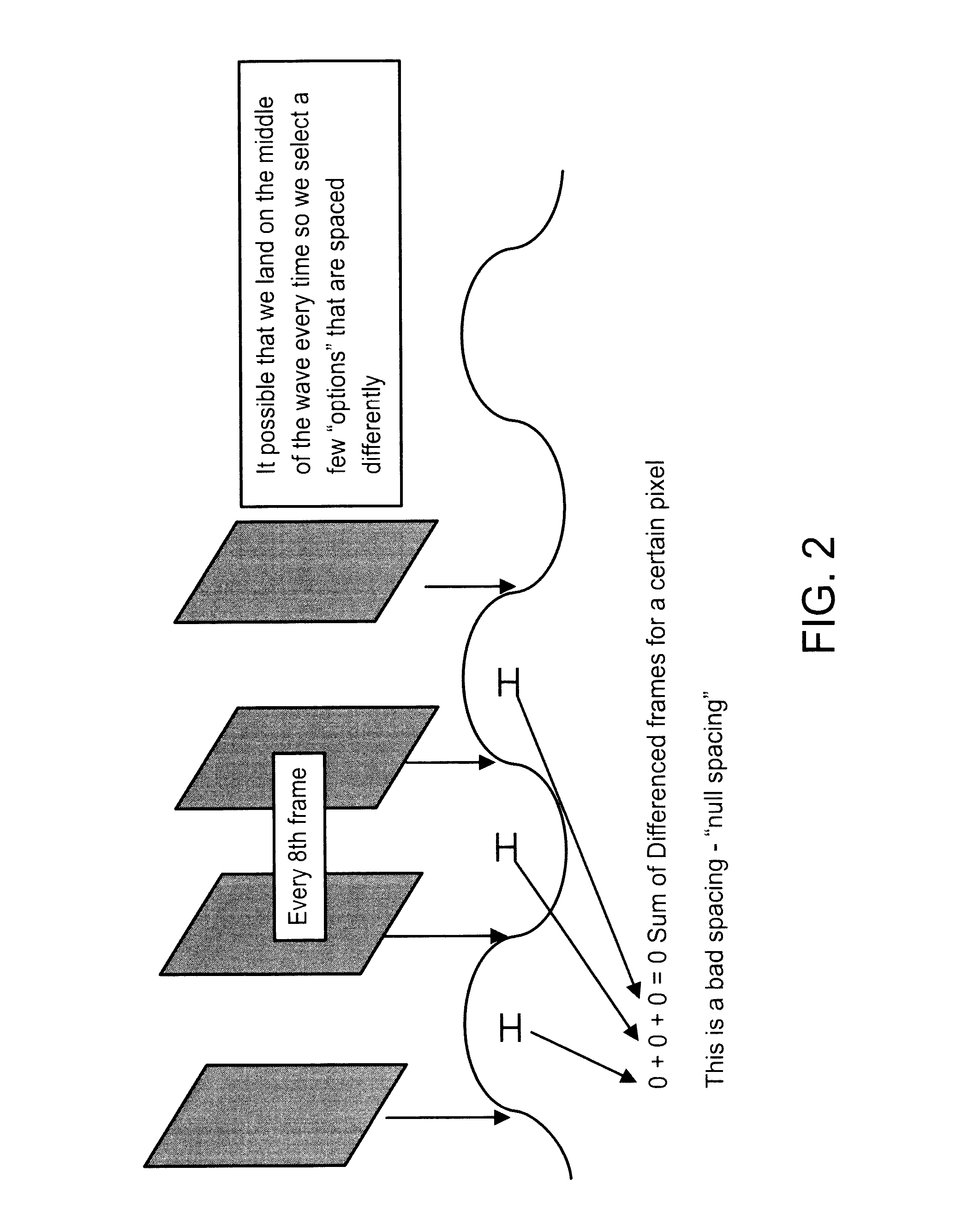
[0264]As noted earlier, Applicants contemplate that the motion-amplification may be done more or less autonomously, with the processor selecting the amplification factor and the playback speed so that the motion will be readily apparent to the naked eye. As an example of the versatility of this approach, a user could download an application to a smart phone, e.g., and then:
1. take a video;
2. upload to a cloud-based server running the motion-amplification process;
3. download the processed video to the same smart phone or have it exported elsewhere for later viewing.
[0265]In this mode, the user is simply a customer of the service and the entire processing operation is autonomous and essentially hidden from the user.
Login to View More PUM
| Property | Measurement | Unit |
|---|---|---|
| frequency | aaaaa | aaaaa |
| physical movements | aaaaa | aaaaa |
| time | aaaaa | aaaaa |
Abstract
An apparatus for visualizing physical movements includes:a device for acquiring video image files;a data analysis system including processor and memory;a computer program operating in the processor to identify an area in the images where periodic motions associated with physical movement of an object may be detected and quantified, and compute a new image sequence in which the motions are visually amplified; and,a user interface that displays the motion-amplified video image of the mechanical component.An associated method for using the apparatus is also disclosed.
Description
CROSS-REFERENCE TO RELATED APPLICATIONS[0001]This application is a continuation in part of U.S. patent application Ser. No. 14 / 757,245 filed on Dec. 9, 2015, entitled “Apparatus and method for analyzing periodic motions in machinery”, which in turn claims the benefit of each of the following Provisional Patent Applications filed by the present inventors: Ser. No. 62 / 090,729, “Optical detection of periodic movement”, filed on Dec. 11, 2014; Ser. No. 62 / 139,127, “Method for determining, comparing, measuring, and displaying phase”, filed on Mar. 27, 2015; Ser. No. 62 / 141,940, “Method and system for analysis of structures and objects from spatio-temporal data”, filed on Apr. 2, 2015; Ser. No. 62 / 139,110, “Adaptive array comparison”, filed on Apr. 14, 2015; Ser. No. 62 / 146,744, “Method of analyzing, displaying, organizing, and responding to vital signals”, filed on Apr. 13, 2015; Ser. No. 62 / 154,011, “Non contact optical baby monitor that senses respiration rate and respiratory waveform”...
Claims
Login to View More Application Information
Patent Timeline
 Patent Type & AuthorityApplications(United States)
IPC IPC(8): G06T7/00H04N5/14G11B27/022G06F3/0484G06V40/20
CPCG06T7/0008G06T7/001G06F3/04847G06T2207/30164G11B27/022G06T2200/24G06T2207/10016H04N5/148G06T2207/20056G06F3/005G06T7/262G01N29/12G01N2291/0289G01N2291/2693G06T7/0004G06T2207/20221G06T7/13G06T7/254G06F16/7335G06V40/20G06V20/46G06F2218/10
InventorHAY, JEFFREY R.SLEMP, MARK WILSON
OwnerRDI TECH INC