Automotive fuel pump

a fuel pump and auto-type technology, applied in the field of fuel pumps, can solve the problems of large noise in the sidi engine, undesirable noise in the fuel system, and inability to meet the needs of the occupants of the vehicle, and achieve the effect of reducing the noise outpu

Active Publication Date: 2016-10-20
HITACHI LTD
View PDF5 Cites 5 Cited by
  • Summary
  • Abstract
  • Description
  • Claims
  • Application Information

AI Technical Summary

Benefits of technology

[0017]Actuation of the solenoid moves the anchor together with the valve member between a fully extended position and a fully retracted position so that the valve is either in a fully open position, or fully closed position, or vice versa. However, when the valve member is in its fully retracted position, the anchor impacts upon the stationary core of the solenoid. Unlike the previously known SIDI fuel pumps, however, when the anchor, and thus the valve member, are in their fully retracted position, a conical surface on the core impacts against a complementary conical surface on the anchor. Thus, unlike the previously known SIDI fuel pumps, the impact force is dispersed partially in a radial direction thus reducing the noise output from the input valve of the pump.

Problems solved by technology

One disadvantage of these previously known SIDI fuel pumps, however, is that the overall fuel system is quite noisy in operation, especially at low engine speeds.
The noise from the fuel system is undesirable for the comfort of the occupants of the vehicle.
Although there are many sources of noise in the fuel system for a SIDI engine, one major cause of engine noise results from the fuel pulsations caused by the reciprocating plunger in the overall fuel system.
A second major source of noise for the SIDI engines is attributable to noise from the opening and closure of the inlet valve for the fuel pump.

Method used


Image

  • Automotive fuel pump
  • Automotive fuel pump
  • Automotive fuel pump

Examples


Embodiment Construction

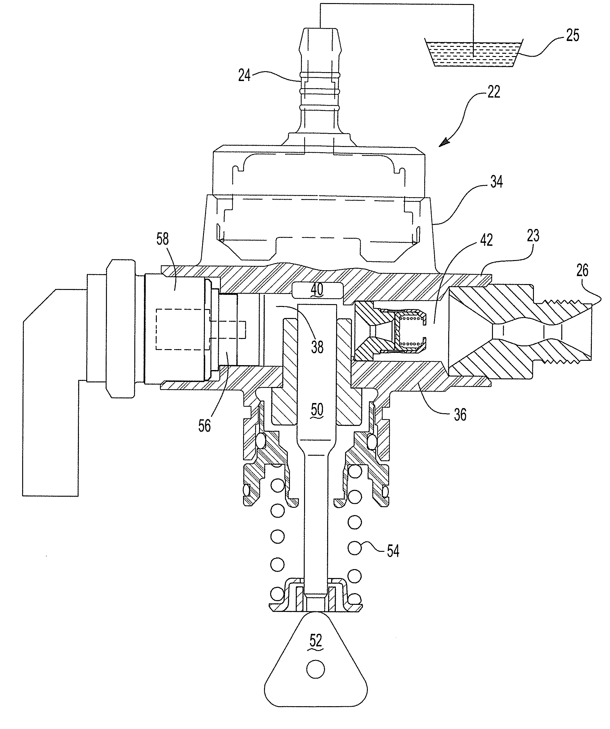
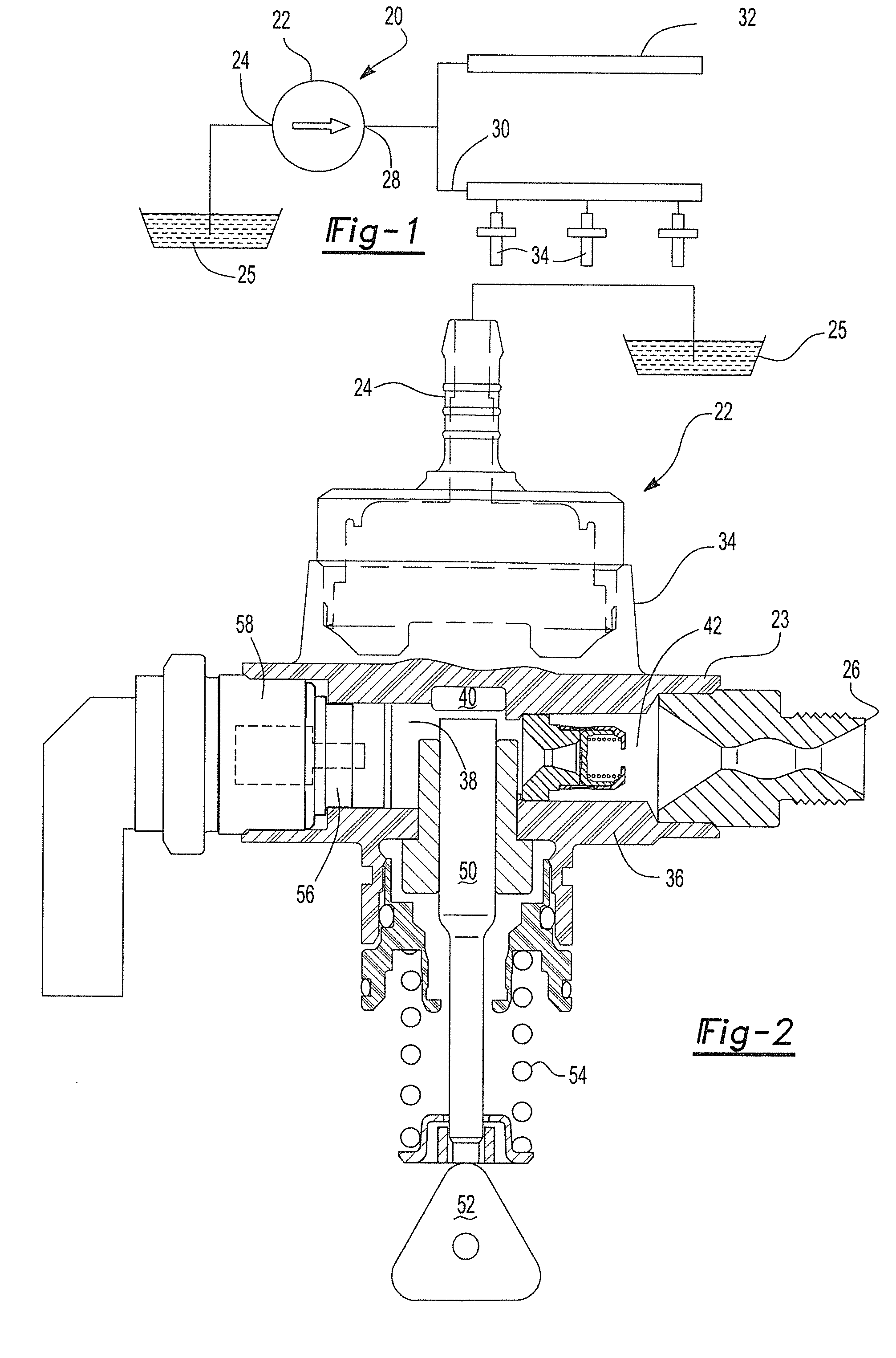
[0028]With reference first to FIGS. 1 and 2, a diagrammatic view of a fuel system 20 for a SIDI engine (not shown) is illustrated diagrammatically. The fuel system includes a fuel pump 22 having a housing 23 and an inlet 24 fluidly connected to a fuel source 25, such as a fuel tank. An outlet 28 from the fuel pump 22 is then connected by fuel supply lines 30 to one or more fuel rails 32. The fuel rails 32 are then fluidly connected to a plurality of fuel injectors 34 which inject fuel directly into the combustion chamber for the engine. Typically, one fuel injector 34 is associated with each combustion chamber.

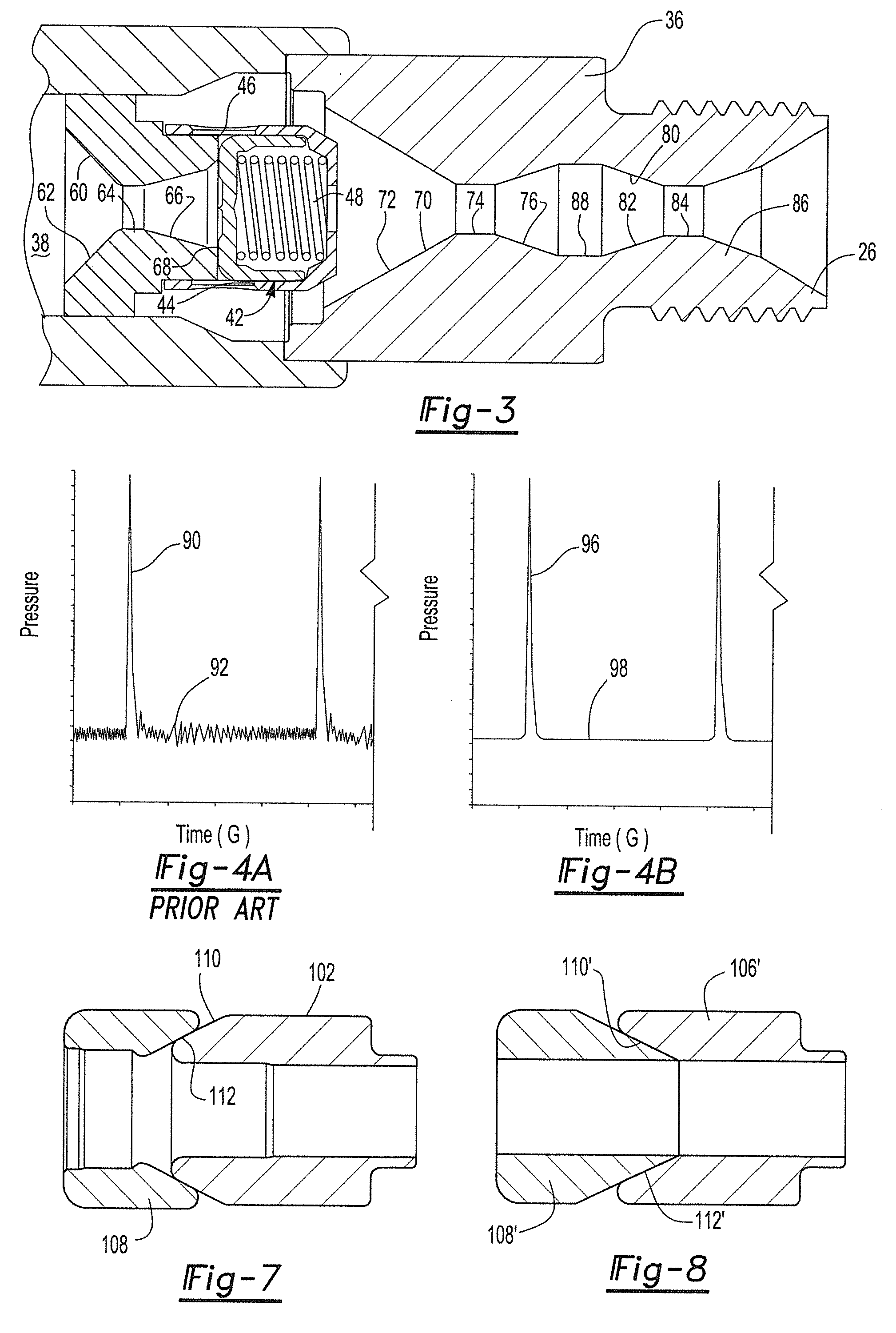
[0029]With reference now to FIG. 2, the fuel pump 22 is there shown in greater detail and includes a housing 36 made of any conventional rigid material, such as steel. A fluid passageway 38 extends through the housing 36 between the inlet 24 and outlet 26 and includes a pump chamber 40 along its length.

[0030]Still referring to FIG. 2, a one way outlet check valve 42 is fluidly...


PUM


Abstract

A fuel pump having a housing defining a pump chamber and an inlet and outlet fluidly connected to the pump chamber. A one way check valve is disposed fluidly in series between the pump chamber and the outlet and is oriented to allow fluid flow from the pump chamber and to the outlet when the check valve is open. A venturi tube is fluidly connected in series between the pump chamber and the outlet which effectively dampens noise pulsations. An inlet valve to the pump chamber has an anchor attached to a valve member and the stationary core. A conical surface on the core abuts against a complementary conical surface on the anchor when the valve is either in its fully open or fully closed position.

Description

BACKGROUND OF THE INVENTION[0001]I. Field of the Invention[0002]The present invention relates generally to fuel pumps and, more particularly, to a fuel pump for a direct injection spark ignition engine.[0003]II. Description of Related Art[0004]Many modem automotive vehicles utilize a direct injection internal combustion engine in which the fuel is injected directly into the combustion chamber by a fuel injector rather than upstream from the intake valves to the combustion chamber. Since the fuel is injected directly into the combustion chamber, the direct injection engines enjoy a higher efficiency and better fuel economy than other types of internal combustion engines.[0005]Since fuel is injected directly into the engine cylinders or combustion chambers, the fuel supply must necessarily be provided at a high pressure sufficient to overcome the pressures existing within the interior of the combustion chambers. Typically, a fuel pump supplies fuel from a source of fuel, such as a fue...

Claims


Application Information

Patent Timeline
Patent Type & Authority Applications(United States)
IPC IPC(8): F02M59/46F04B53/16F04B53/10F04B53/14F04B19/22F04B7/00
CPCF04B7/0076F04B53/10F04B53/16F04B19/22F04B53/14F02M59/464
Inventor AVIREDDI, PRASHANTHSEERA, NIKHILINOUE, AKIRA
Owner HITACHI LTD
Why Eureka
Try Eureka