System and Method for Estimating Time of Arrival (TOA)

Active Publication Date: 2016-10-20
NESTWAVE SAS
View PDF5 Cites 12 Cited by
  • Summary
  • Abstract
  • Description
  • Claims
  • Application Information

AI Technical Summary

Benefits of technology

The patent describes a method to estimate the time of arrival (TOA) of signals. The inventor found that the matched filter is not always the right strategy for estimating the TOA when certain conditions are met. The method uses a near-causal filter that ensures the first tap is not interfered by subsequent taps, making it easier to identify the first tap and calculate the TOA. The method also involves analyzing the signal properties and selecting a second adaptation to replace the previously generated first waveform, if available. The technical effect of this method is to improve the accuracy of estimating the TOA of signals.

Problems solved by technology

As shown in FIG. 1, a difficulty in the estimation of time of arrival arises from the fact that the radio wave has multiple paths from the transmitter 10 to the receiver 12.
It is therefore very difficult to use simple signal processing to find the exact time of arrival by comparing the reference waveform 34 to the filtered waveforms.
However, such techniques are either simple to process and inaccurate or, like the Maximum Likelihood (ML) algorithm, accurate but very processing intensive, and therefore expensive.

Method used


Image

  • System and Method for Estimating Time of Arrival (TOA)
  • System and Method for Estimating Time of Arrival (TOA)
  • System and Method for Estimating Time of Arrival (TOA)

Examples


Embodiment Construction

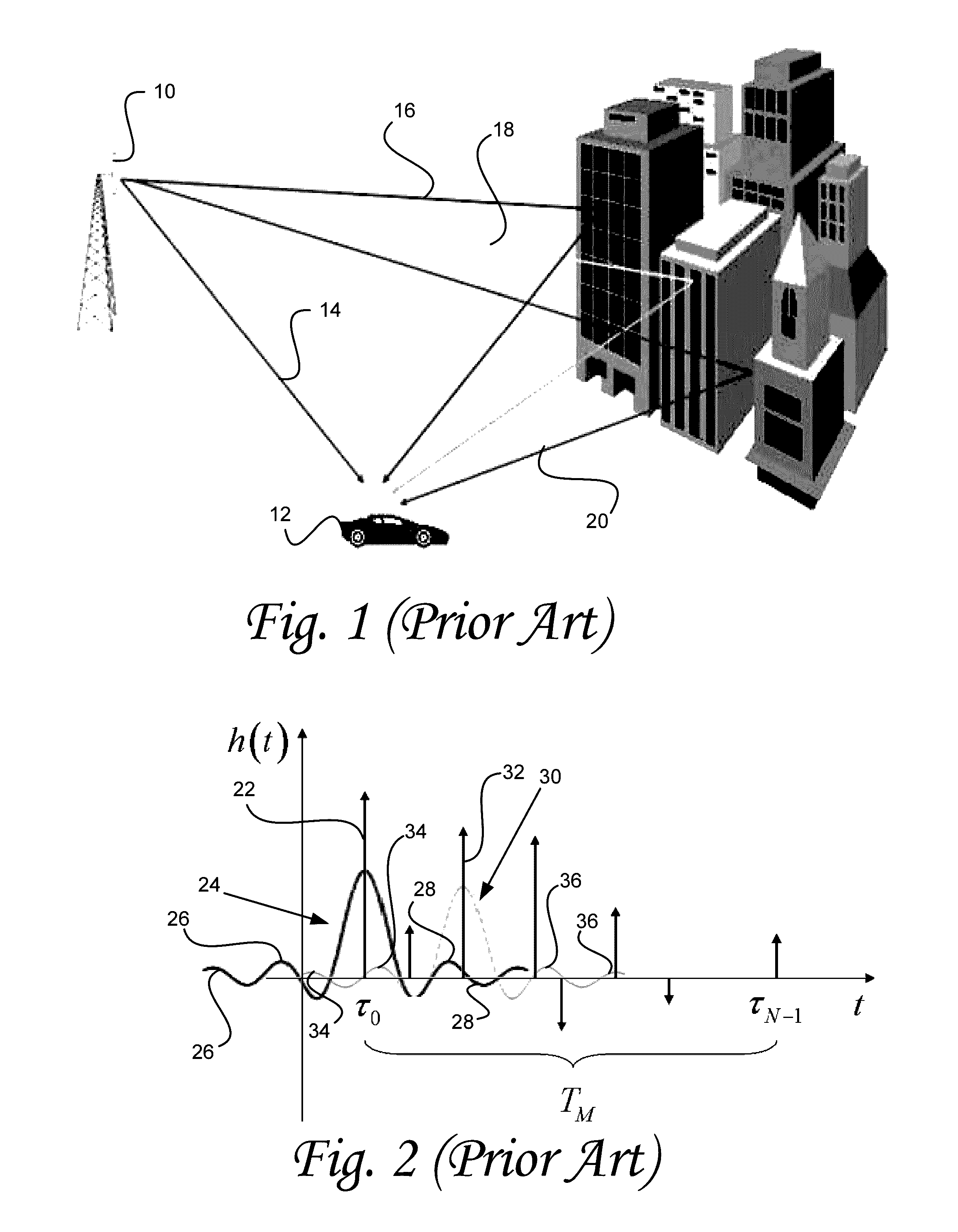
[0008]The impulse response shape is usually a sinc, a raised cosine, or some relatively slowly decaying waveform symmetrical around the origin. The reason for the symmetry is that the frequency domain matched filter creates a zero phase signal symmetrical in time domain. The matched filter is necessary to optimize symbol detection in noisy environment (used in conjunction with an equalizer). In this problem, the information is carried by all the taps.

[0009]However, the inventor has found that for estimating the TOA where the information is carried by the first tap only, and whose phase has no relevance in this case, the matched filter is not necessarily the right strategy. Some embodiments of the present invention, therefore, relate to the use of a near-causal filter (near zero energy before the origin) which ensures that the first tap is not interfered (or less interfered) by subsequent taps. Filtering a signal in this manner makes it easier to identify the first tap, and therefore...


PUM


Abstract

A technique is provided for estimating time of arrival of a signal transmitted as a pulse and received as a sum of pulses. The received signal is filtered with a novel filter that lowers the early side lobes of the received signal to noise level. A first energy rise point is identified at a point of the main lobe of the filtered received signal, at which the energy is higher than the noise by a predetermined level. Starting from the identification of the first energy rise points, the time of arrival is estimated via curve matching, in which the shape of the filtered received signal is matched to the shape of composed by a sum of one or more reference curves that are shifted both in time and in energy. The reference curves are found by applying to the transmitted signal the same filter applied to the received signal.

Description

CROSS-REFERENCES TO RELATED APPLICATIONS[0001]The present application claims priority to U.S. Provisional Application Ser. No. 61 / 942,360 filed on Feb. 20, 2014, U.S. Provisional Application Ser. No. 62 / 051,566 filed on Sep. 17, 2014, U.S. Provisional Application Ser. No. 62 / 080,654 filed on Nov. 17, 2015, U.S. Provisional Application Ser. No. 62 / 099,158 filed on Jan. 1, 2015, and U.S. Provisional Application Ser. No. 61 / 989,029 filed on May 6, 2014 which are hereby incorporated herein by reference in their entirety.TECHNICAL FIELD[0002]The present invention, in some embodiments thereof, relates to signal processing, and more particularly, to systems and methods for determining time of arrival (TOA).BACKGROUND OF THE INVENTION[0003]Time of arrival estimation is the estimation of the travel time of a radio signal from a single transmitter to a remote single receiver. The travel time may be expressed in units of time or in units of distance, as the distance between the transmitter and...

Claims


Application Information

Patent Timeline
IPC IPC(8): G01S5/06H04B17/336G01S5/02H04L27/26
CPCG01S5/06G01S5/0252H04B17/336H04L27/2628G01S5/0221G01S11/02G01S5/0218
Inventor CHRABIEH, RABIHFRANOVICI, BOGDANSLOCK, DIRK
Owner NESTWAVE SAS
Why Eureka
Try Eureka