Laminated glass

a technology of laminated glass and film, applied in the field of laminated glass, can solve the problems of reducing transparency of pet films, deteriorating appearance, and difficult to say that laminated glass has sufficient durability for automobile and building use, and achieves the effect of suppressing the deterioration over time of spd films and excellent switching transmittance of ligh

Inactive Publication Date: 2016-10-27
ASAHI GLASS CO LTD
View PDF0 Cites 29 Cited by
  • Summary
  • Abstract
  • Description
  • Claims
  • Application Information

AI Technical Summary

Benefits of technology

[0012]According to the present invention, it is possible to provide a laminated glass with an SPD film excellent in property of switching transmittance of light for a long term by suppressing deterioration over time of the SPD film, in particular, deterioration due to intrusion of moisture at an end portion.

Problems solved by technology

However, even by using these techniques, the intermediate bonding film in a frame shape, when its width is small, for example, 10 mm or less, does not have sufficient durability against the intrusion of moisture from the end face of the laminated glass, leading to deterioration.
Therefore, it is hard to say that the laminated glass has sufficient durability for usage of automobile and building even if using these techniques.
However, in the case of using the PET film, bubbles are likely to be generated between the end face of the PET film in a frame shape and the end face of the SPD film in contact with the PET film and may degrade the appearance.
For example, the PET film has a problem of reduction in transparency and increase in cost when it has such a thickness.

Method used


Image

  • Laminated glass
  • Laminated glass
  • Laminated glass

Examples


experimental example 1

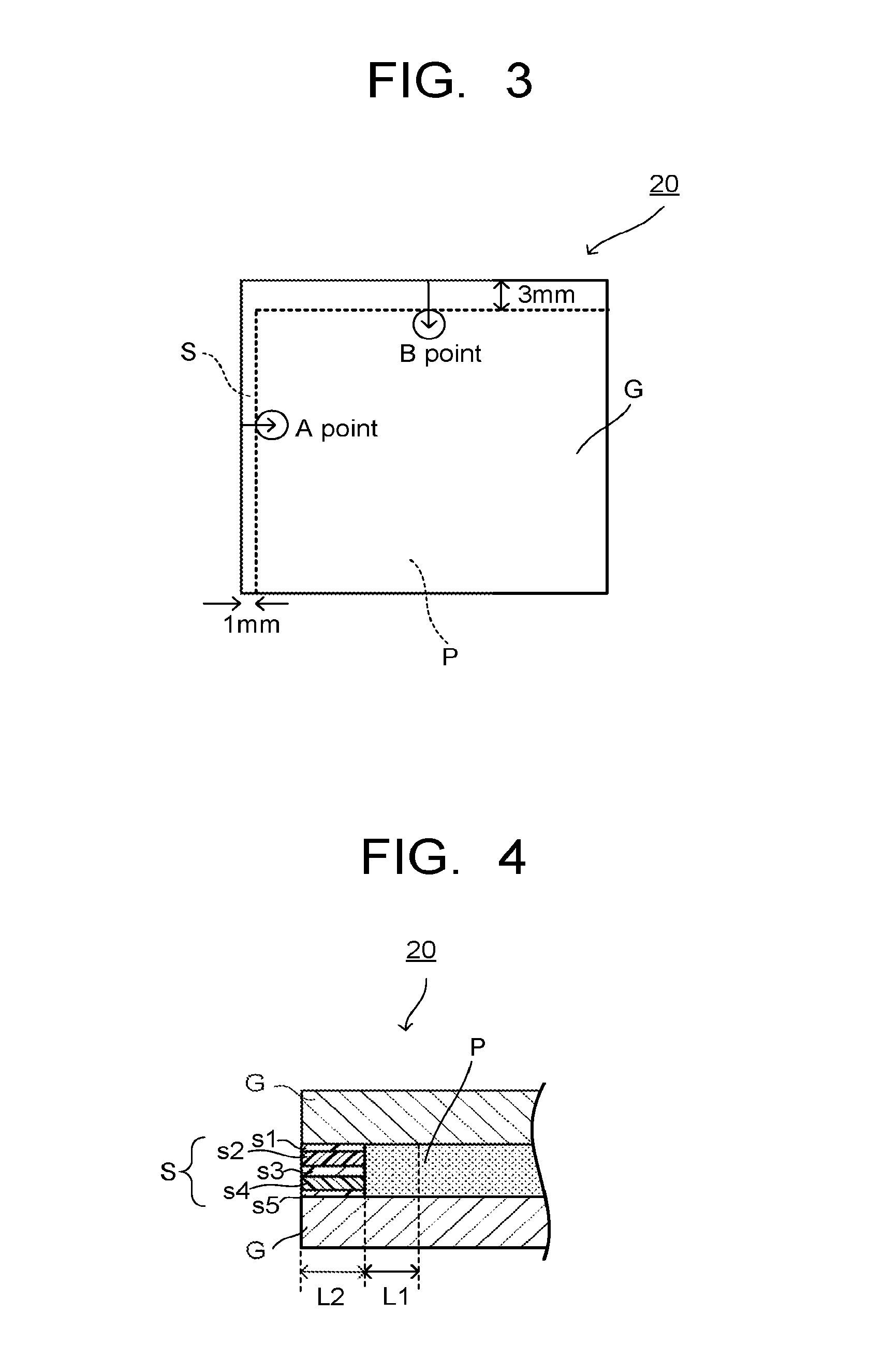
[0090]An evaluation sample having PVB whose moisture content was measurable was fabricated in place of the SPD film as described below, and the moisture-proof property of the barrier layer applied to the laminated glass of the present invention was evaluated.

[0091](Fabrication of Evaluation Sample)

[0092]An evaluation sample 20, whose front view is illustrated in FIG. 3 and whose cross-sectional view at the end portion is illustrated in FIG. 4, was fabricated as follows. Between two glass plates G (2 mm thick, 100 mm squares) made of soda lime glass, a 99×97 mm and 0.8 mm thick of PVB film (manufactured by Eastman Chemical Company, RK11 (brand name)) P was arranged so that its two sides were aligned with two sides of the glass plates G. Further, a barrier layer S in a shape to compensate for the cutout portion of the PVB film P between the two glass plates G and having band-shaped regions formed in an L-shape was arranged. Note that the barrier layer S is arranged such that the end f...

example 1

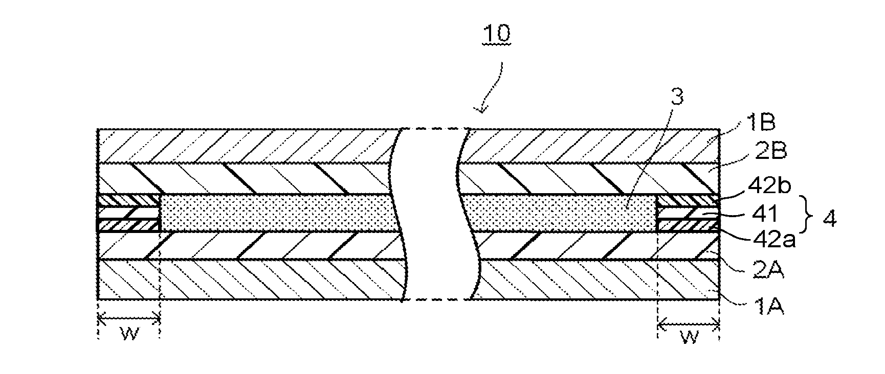
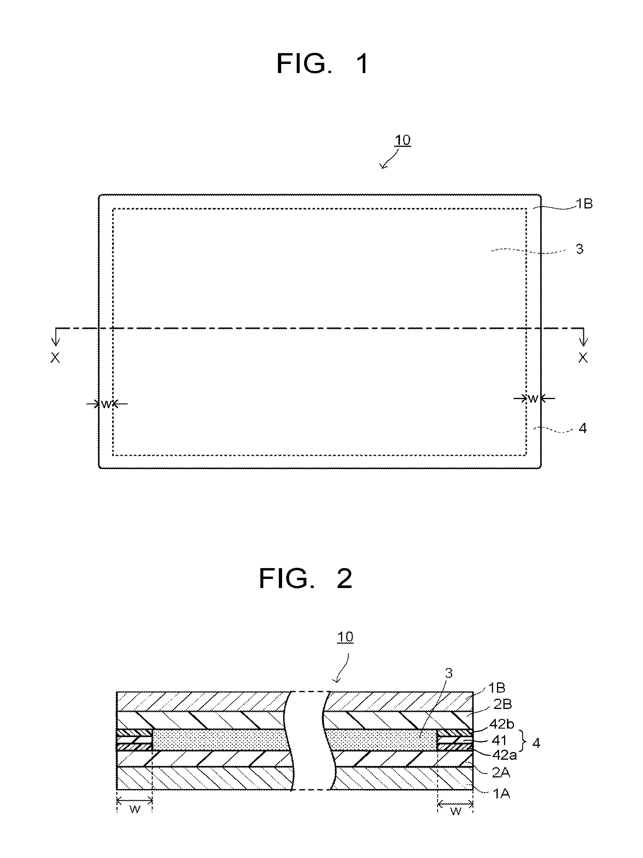
[0099]Laminated glass 10s having the same configuration as that of the laminated glass 10 described as one embodiment in the above and illustrated in FIGS. 1, 2, whose front view is illustrated in FIG. 5 and whose cross-sectional view taken along a line Y-Y is illustrated in FIG. 6, was fabricated as follows.

[0100](Fabrication of Laminated Glass)

[0101]On one glass plate 1A (100 mm×100 mm, 2 mm thick) made of soda lime glass, the intermediate bonding layer 2A composed of an EVA film (manufactured by TOSO NIKKEMI CORPORATION, Mersen G7055 (brand name)) of 100×100 mm, 0.4 mm thick was arranged so that its four sides were aligned with four sides of the glass plate 1A.

[0102]Further, on the intermediate bonding layer 2A, the barrier layer 4 (having inner dimensions of 94×92 mm, and widths of 1 mm, 3 mm, 5 mm, 5 mm at four sides respectively) in a frame shape with the same outer dimension as those of the glass plate 1A was arranged so that its four sides were aligned with the four sides of...


PUM

PropertyMeasurementUnit
thicknessaaaaaaaaaa
RHaaaaaaaaaa
temperatureaaaaaaaaaa

Abstract

To provide laminated glass with a suspended particle device (SPD) film excellent in property of switching light transmittance for a long term by suppressing deterioration over time of the SPD film, in particular, deterioration due to intrusion of moisture at an end portion. A laminated glass includes: a pair of glass plates opposing each other; a pair of intermediate bonding layers in contact with opposing surfaces of the pair of glass plates respectively; a SPD film arranged in a predetermined region in a region corresponding to a region except at least a part of band-shaped regions of peripheral edge portions of a main surface of the glass plate, between the pair of intermediate bonding layers; and a barrier layer in a laminated structure including a low-moisture permeable layer and a bonding layer, arranged between the pair of intermediate bonding layers in a manner to correspond to the band-shaped regions.

Description

CROSS REFERENCE TO RELATED APPLICATION[0001]This application is based upon and claims the benefit of priority from the prior Japanese Patent Application No. 2015-089773, filed on Apr. 24, 2015; the entire contents of which are incorporated herein by reference.FIELD[0002]The present invention relates to a laminated glass and, in particular, to a laminated glass with a suspended particle device film.BACKGROUND[0003]As window glass intended for building and vehicle, a glass (smart glass) capable of electrically switching the transmittance of light by on / off of a power supply switch is known. As a functional material used for such a smart glass, there is a suspended particle device (hereinafter sometimes referred to as “SPD”) film.[0004]The SPD film is configured such that a polymer layer containing suspended particles which can be oriented by application of voltage thereto is sandwiched between two films coated with transparent conducting films. The smart glass is fabricated by sealing...

Claims


Application Information

Patent Timeline
Patent Type & Authority Applications(United States)
IPC IPC(8): E06B3/67G02F1/17E06B9/24B32B17/10
CPCE06B3/67B32B17/10165B32B17/10036G02F1/172E06B2009/247B32B2307/7265B32B2307/40B32B2551/00E06B9/24B32B3/08B32B7/10B32B17/06B32B33/00B32B17/10532B32B17/10761B32B17/10788G02F1/1339B32B17/10302
Inventor MIYASAKA, SEIICHIAOKI, TOKIHIKO
Owner ASAHI GLASS CO LTD
Why Eureka
Try Eureka